Tii 759 User Manual
Tii Equipment
tii P/N: 92204701
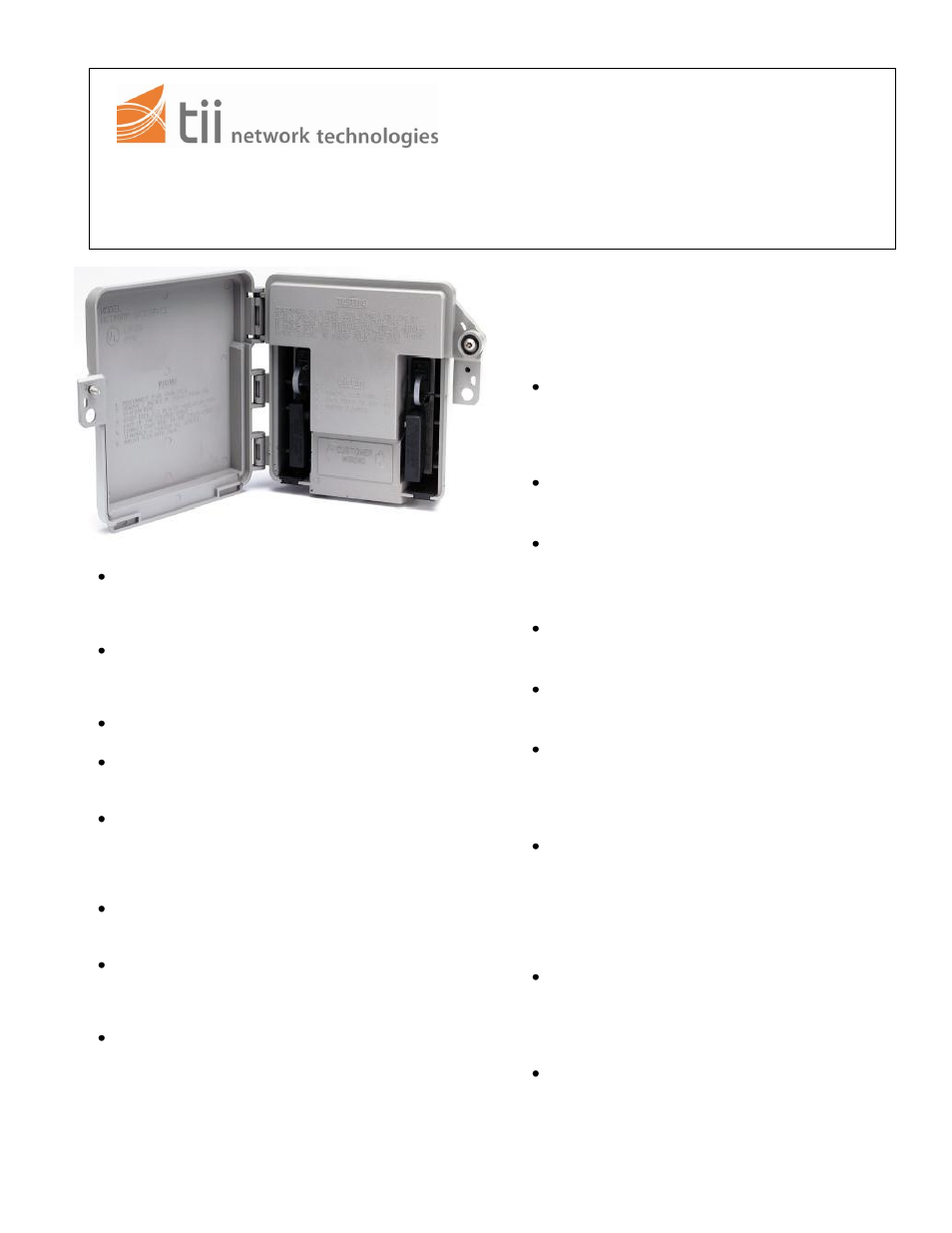
tii 759
141 Rodeo Drive
Universal Network Adapter
Edgewood, NY 11717
1/08 Rev B
Toll Free 888.844.4720
www.tiinettech.com
INSTALLATION NOTE
1. GENERAL
The tii 759 Universal Network Adapter is
designed to retrofit either one pair or two pair
station protector housed in an AT&T 8813B
Service Enclosure.
The tii 759 1 is furnished complete with
customer wiring bridge / RJ-11 modular jack with
spade tipped leads for one pair. The tii 759 2 is
similarly equipped for two pair.
No special tools are required to install or
maintain this product.
The tii 759 is equipped with a cover tab that
allows the customer to lock the unit, but allows
the Telco to override the lock.
The interior has a set of hinged covers that keep
the Telco protector modules and station
electronics out of the customer’s view and touch.
They may be accessed with a
3
/
8
” hex head
terminal wrench or a pin-in-head wrench.
The customer wiring bridge and the RJ-11
modular jack are press fit and readily field
replaceable.
The tii 759 Series Universal Network Adapter is
equipped with four card slots which allow a
variety of station electronics to be fitted to the
customer line.
If the hook up wire or OSP cable is physically
larger than No. 22AWG, a fusing conductor of
No. 22AWG solid copper wire with thermoplastic
insulation or No. 22AWG copper clad steel
(bridle wire) shall be employed.
1. WARRANTY
See tii Warranty. If this unit fails during the
warranty period, the factory should be requested to
authorize return. Return the unit prepaid when
authorization is received. Units that fail due to
abuse or normal wear should be discarded.
2. INSTALLATION
– PREPARATION
If there are any outboard electronic packages
mounted beside the AT&T 881B station protector,
they may have to be moved. The tii 759 Series
Adapter requires a clear space of three inches on
both sides and top of the station protector.
After ensuring that adequate space is available to
mount the tii 759 Adapter, remove and discard
the 8813B cover.
Inspect the protector, wiring and ground
connection. Perform any maintenance required by
local practice.
3. INSTALLATION
– NO ELECTRONICS
Carefully remove the inside wires from the
protector and pull them out through the grommet.
Carefully bend them away from the installation.
Remove the tii 759 Adapter from the box and
inspect if for damage. If the unit is damaged,
obtain another unit.
Using a screwdriver loosen the screw below the
hex head or pin-in-head security screw and open
the outer door. Then with a
3
/
8
” hex head terminal
wrench or a pin-in-head wrench, loosen the
security screw and open the inner door.
Place the tii 759 A
dapter over the “B” closure
base about one third of the way up and all the
way to the wall. Then slide the tii 759 Adapter
down until you hear the unit snap and lock into
place. The tii 759 is designed to fit snugly over the
base of the AT&T 8813B but does not require
excessive force to install.
Locate the RED and GREEN spade tipped wires
coming from the RJ-11 jack on the right hand side
and terminate them on the Ring and Tip terminals
of the upper protector module respectively.
Observe polarity.
If the tii 759 Adapter is fitted for two lines, and the
second protector module is in place, locate the
RED and GREEN spade tipped wires coming
from the RJ-11 jack on the left hand side.
Terminate them on the ring and tip terminals of
the second protector module. Observe polarity.