Tii 761-4T-12K User Manual
Page 2
7. Dress the wires properly inside the junction
box and secure the 761-4T-12, 761-4T-12K to
the junction box using the supplied #6 oval
head screws (See Figure 3).
The 761-4T-
12K also includes (2) #6 x 2” lg.
oval head screws with ferrules.
Figure 3
8. Connect the existing phone and DSL modem
into their respective RJ-11 receptacles on the
front face plate (See Figure 4).
Figure 4
Existing Construction Installation
1.
Cut drywall 2” W x 3.5” L in the location where
the 761-4T-12, 761-4T-12K will be mounted.
Prior to cutting hole confirm that there are
no obstructions behind wall.
2. After drywall has been cut, install a metal cut-
in ring wall mounting plate, (available
separately from tii). Bend the two mounting
tabs behind the drywall and secure the
mounting plate with the supplied drywall
screws, (See Figure 5). Align the mounting tab
slots while tightening the screws.
Figure 5
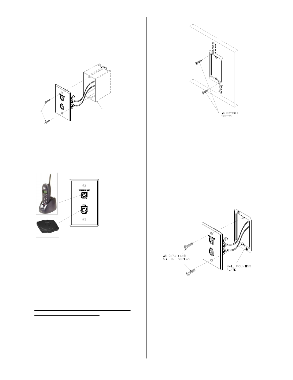
3. Dress the wires properly inside the wall
mounting plate and secure the 761-4T-12,
761-4T-12K to the wall mounting plate using
the supplied #6 oval head screws
(See Figure 6).
The 761-4T-
12K also includes (2) #6 x 2” lg.
oval head screws with ferrules.
Figure 6
#6 OVAL HEAD
MACHINE SCREWS
EXISTING JUNCTION
BOX