Tii VIS-2 User Manual
Page 2
tii P/N: 92225501
1). Pins 1 and 4 must be used for
Intercom Input.
4.4 Wire the other end of the cable to the
intercom input and other phone connections
in multiple dwelling units.
5. TESTING
Note: Hardware reset is required to
switch device to its initial state after
installation. The initial state for the VIS-2
is intercom mode.
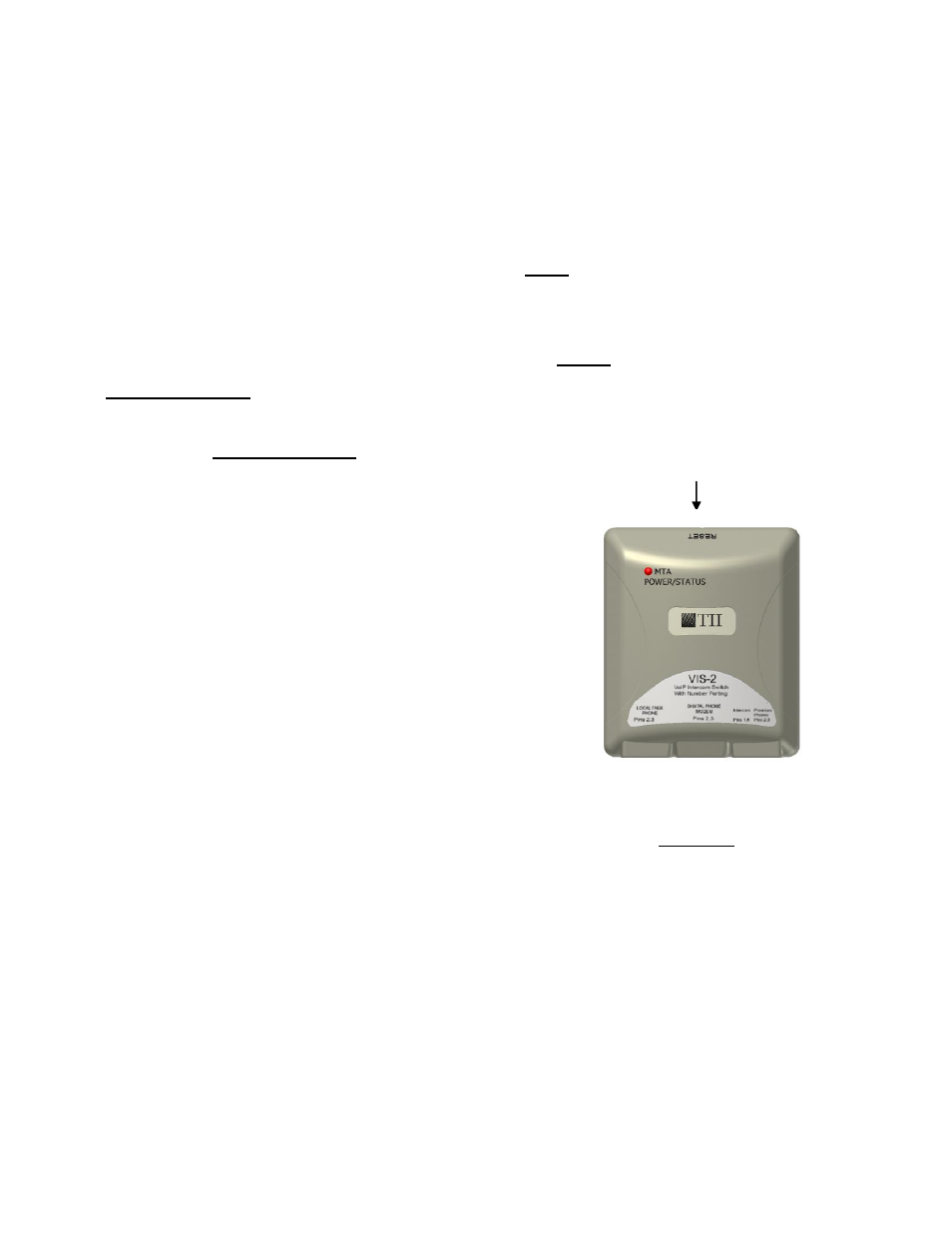
5.1 To reset this unit:
Insert an RJ11 plug from the MTA lead into
the “Digital Phone Modem” jack. Depress the
reset button within 3 seconds of powering
the jack. (Figure 2).
5.2 With power applied after the reset switch on
the VIS-2 is pressed the unit is in Intercom
Mode. The LED should be flashing Red.
5.3 The VIS-2 will automatically switch to VoIP
Mode after the second ring of the VoIP line.
The LED should be flashing Green. Once
the VIS-2 has been switched to VoIP Mode it
will stay in this mode and only temporarily
switch over to answer intercom calls.
5.4 When the Intercom is ringing and VoIP is on
the hook, the VIS-2 will switch to intercom to
allow the customer to answer it. After
answering the intercom or the ringing has
stopped, the VIS-2 will switch back to VoIP
mode. The LED should be flashing Orange.
5.5 To answer the intercom when the VoIP is off
the
hook,
press
the
hook
switch
momentarily. The VoIP line will be placed on
hold and at the same time switch the VIS-2
to intercom mode. The LED should be
flashing Orange. When you are finished with
intercom press the hook switch momentarily
to recover the status of the VoIP line.
Note: The reset switch on the VIS-2 has to
be pushed and held for a few seconds after
power-up in order for the device to switch to
Intercom Mode (Figure 2).
5.6 Gently using a small blunt object push
the reset button, see Figure 2 for
location.
CAUTION:
TO AVOID PERMANENT DAMAGE TO RESET
BUTTON DO NOT USE EXCESSIVE FORCE
OR A POINTED OBJECT TO ACTIVATE THE
RESET BUTTON.
Reset Button Opening
Figure 2