Tii 96-00-1 SERIES User Manual
Page 2
TII P/N: 92222101
3.2.8
Dress wires around customer security cover.
3.2.9
Start wiring from the bottom left rocker.
3.2.10 Hold the customer voice telephone wires between
thumb and index finger (approx. 1/8” separation
between wires).
NOTE: IDC’s accept 22-26 AWG solid wire. Wires should
be aligned to the corresponding holes. Green wire to the
“T” (GRN) labeled wire guide and the Red wire to the “R”
(RED) labeled wire guide.
3.2.11 Insert wires into wire guides at the same time until
they bottom out.
3.2.12 While holding wires in wire guides, terminate
rocker with thumb (lower rocker all the way).
3.2.13 Terminate additional voice pairs to lower right and
upper left rockers as required (See Figure 1).
3.2.14 Terminate the DSL Data wire pair at upper right
locker only.
3.2.15 Assure all rockers are in the down position and
close customer security cover.
4.0 TESTING
4.1 CUSTOMER TELEPHONE WIRE INTEGRITY
TESTING
4.1.1
Open customer security cover.
4.1.2
Insert RJ-11 plug into customer test jack to isolate
telco from customer wiring.
4.1.3
Lift all rockers to the up position. Insert customer
telephone wire into rocker wire guides as shown
(see Figure 3).
4.1.4
Terminate rocker (lower rocker all the way).
4.1.5
Using an ohmmeter, insert probes into test ports as
shown (see Figure 3), and check for continuity.
4.1.6
Customer wiring is ok if meter does not indicate a
short circuit.
4.1.7
Repeat test for all four sets of customer telephone
wires. If the customer telephone wire does not
show a meter reading, then it has a break in it.
4.1.8
Close customer security cover and inform
customer.
4.2 CENTRAL OFFICE SIGNAL TESTING
4.2.1 Open customer security cover.
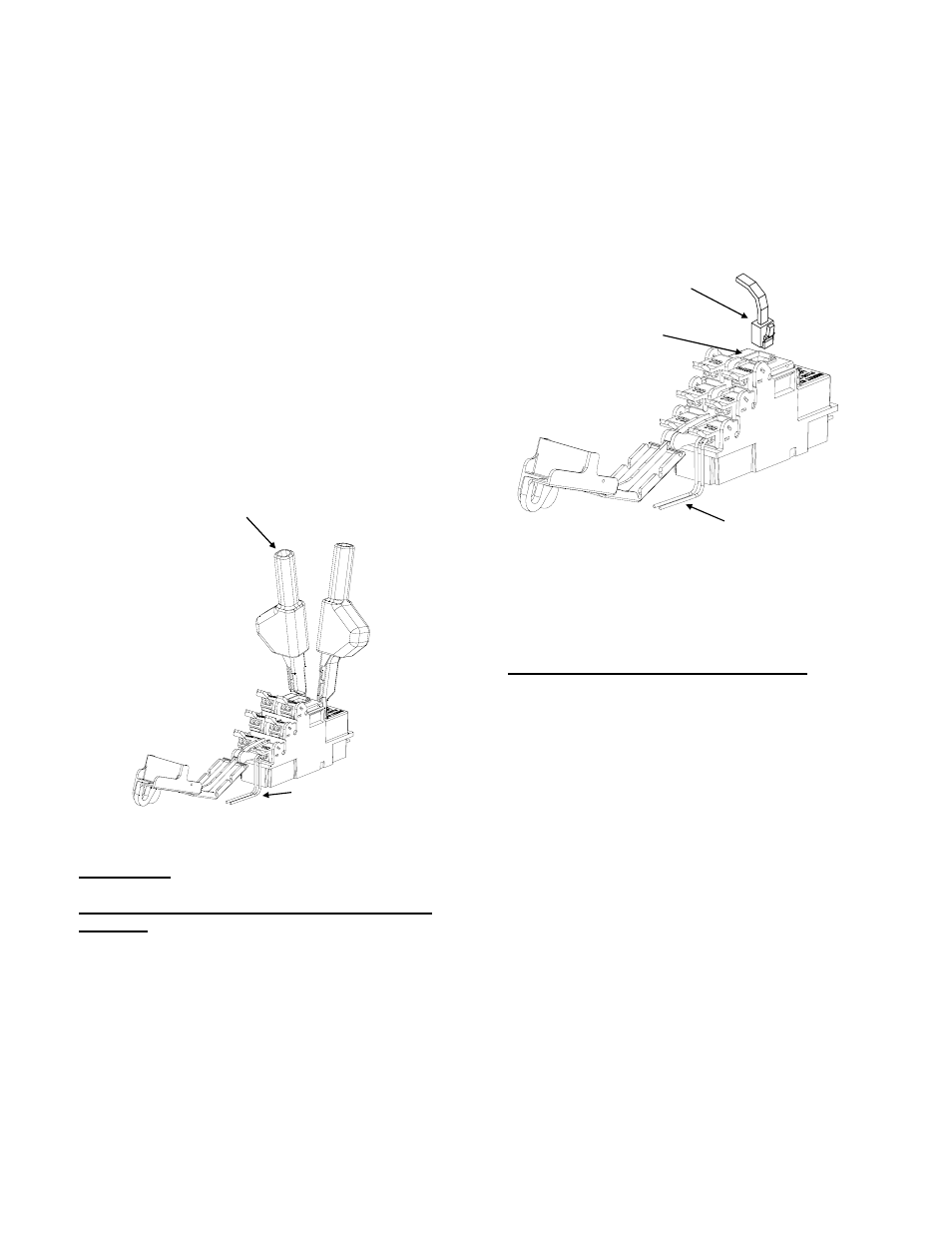
4.2.2 Using a working telephone, insert telephone RJ-11
plug into customer test jack (see Figure 4).
4.2.3
Wait a few seconds, lift receiver, and listen for
tone.
4.2.4
If tone is not present, then contact central office
service provider.
4.2.5
If dial tone is present, then a problem exists in the
customer telephone wires.
CUSTOMER TELEPHONE WIRES
Figure 3
TEST PROBES
Figure 4
RJ11 PLUG FROM A GOOD
WORKING TELEPHONE
CUSTOMER TEST JACK
CUSTOMER TELEPHONE WIRES