Tii ISB PLATE User Manual
Page 2
4. Lift the Line Input rocker for the Telco service
wires to the full up position. DO NOT strip
wires (See Figures 2 & 3).
5. Insert the Telco service wires into the wire
guides simultaneously until they bottom-out.
While holding wires in position, terminate into
Line Input rocker by lowering to the full down
terminated position (See Figures 2 & 3).
Figure 2
6. Lift the From Enter System rocker to its fully
upright position. Insert the enter system output
wires into the From Enter System marked
rocker. While the wires are fully inserted, lower
the rocker fully down to complete the Enter
System Output wire termination (See Figures
2 & 3).
7. Terminate the customer wiring onto the Line
Output rocker on the right side of the module.
Insert wires into the customer rocker holes.
While assuring that the wires are fully inserted
lower the rocker to its fully seated position
(See Figures 2 & 3).
Figure 3
8. Terminate wire pair serving as input to enter
system at the rocker labeled To Enter System
on the right side of the module. Follow the
procedure described above for the wire pair
termination (See Figures 2 & 3).
9. To keep wire pairs organized, route them
through the molded wire guides (See Figure
2).
10. Connect test clips to input test port and make
sure POTS line dial tone is present. Repeat
testing for the output connections using output
test port.
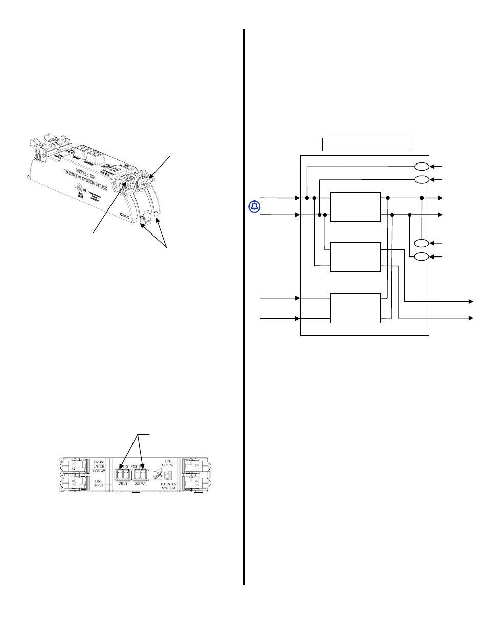
11. Refer to Figure 4 for the ISB module functional
schematic.
Figure 4
TEST POINTS
Terminated Rocker
Full Up Position
Wire Guides
FUNCTIONAL DIAGRAM
HIGH PASS
FILTER
(HPF)
LOW PASS
FILTER
(LPF)
LOW PASS
FILTER
(LPF)
INPUT TEST
PORT (TIP)
INPUT TEST
PORT (RING)
LINE OUTPUT
TELCO LINE
INPUT (TIP)
TELCO LINE
INPUT (RING)
FROM ENTER
SYSTEM (TIP)
FROM ENTER
SYSTEM (RING)
TO ENTER
SYSTEM (TIP)
TO ENTER
SYSTEM (RING)
OUTPUT TEST
PORT (TIP)
OUTPUT TEST
PORT (RING)