Reset – Tii 170-06-04 User Manual
Page 2
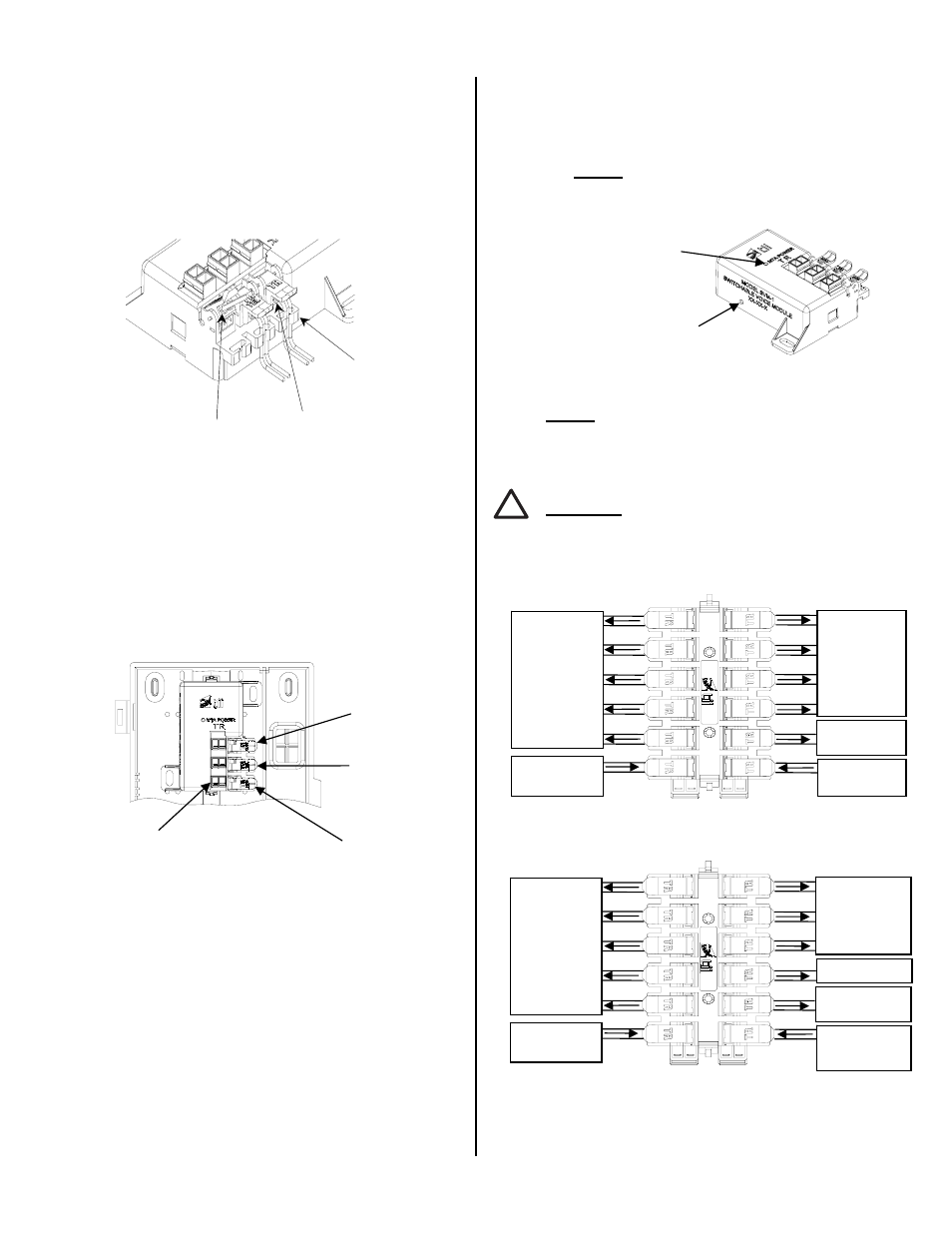
2. Insert the digital voice service wires from
ATA/EMTA through the grommets and into
wire guides simultaneously until they bottom-
out. While holding wires in position, terminate
them into the MTA (Blue) rocker by lowering it
to the full DOWN position (See Figures 2 & 3).
If the ATA/EMTA is supplying power to the
SVM, the green MTA power LED provided on
the line will start to blink.
Figure 2
3. Disconnect the customer premise wiring from
the Telephone Network Interface Device
(NID). Straighten the ends of the wires, cut
kinked and stripped ends. Pass the customer
telephone wire through the enclosure (Cust)
grommet. Lift the Green/Red rocker to full up
position. Insert wires into the Cust wire rocker
holes. While assuring that wires are fully
inserted, lower the rocker to fully seated
position (See Figure 3).
Figure 3
4. Connect the Telco Service using a wire pair
from the Telephone NID to the rocker labeled
TEL (orange). Follow the procedure described
above for the wire pair termination (See
Figures 2 & 3).
5. To keep the wire pairs organized, route them
through the molded wire looms. (See Figure
2).
6. Dress the wires properly inside the housing
and close the cover. A suitable tie wrap can
be used for added security.
7. IMPORTANT: This unit MUST be reset during
initial installation. For resetting the MTA
Power, refer to the reset instructions below.
Reset
1. Confirm that the power is connected to the
MTA (Blue) rocker of SVM module.
2. Gently push the reset button once with a blunt
object to ensure the service to the customer is
from the Telco Service Provider (See Figure
4).
Figure 4
NOTE: THE RESET SWITCH IS DISABLED
DURING RINGING VOLTAGE PRESENCE AND
TEN SECONDS AFTER THE LAST RINGING
VOLTAGE.
CAUTION: TO AVOID PERMANENT DAMAGE
TO RESET BUTTON, DO NOT USE EXCESSIVE
FORCE OR A POINTED OBJECT TO ACTIVATE
THE RESET BUTTON.
68T-2S
68T-2S-4
Figure 5
Terminated rocker
Wire loom
Full Up Position
Test Points
Digital Voice
Service Wires
Telco Wires
Customer Wiring
LED MTA
Power Indicator
*Reset Button
Opening
M
T
A
S
-OUT
S-
IN
Customer
Telephone
Wires
Customer
Telephone
Wires
Digital Voice
Service Input
Security
System Output
Security System
Input
M
T
A
S
-OUT
S-
IN
L2 Customer
Premise Wiring
L1 Customer
Premise Wiring
L1 Digital Voice
Service Input
L1 Security
System Output
L1 Security
System Input
L2 Input
!
√
√