Horn and fixture alignment – Sonics 2055-Press User Manual
Page 17
• • • • • • • • • • • • • • • • • • • • • • • • • • • • • • • • • • • • • • • • • • • • • • • • • • • • • • • • • • • • • • • • • • • • • • • • • • • • • • • • • • • • • • • • • • • • • • • • • • • • • • • • • • • •
I N S T R U C T I O N M A N U A L • M O D E L 2 0 5 0 / 2 0 5 5
16
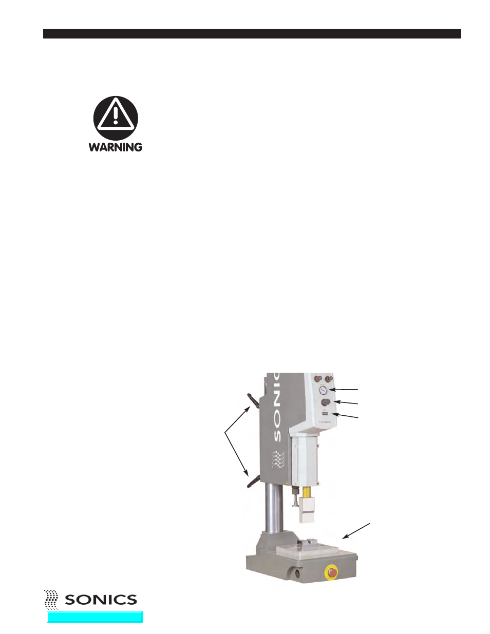
HORN AND FIXTURE ALIGNMENT
For maximum productivity, the clearance between the horn and the part
should be at a minimum. However, adequate clearance should be provided to
enable easy loading and unloading of the part from the holding fixture. The
maximum stroke distance is 4" (101.6 mm). Ensure that the horn does not
contact the part when the head is close to the limit of its down travel distance.
Otherwise, the horn may not have sufficient distance to travel downwards to
achieve a full depth of weld. Set welding height as follows:
First, position the holding fixture loosely on the machine base using 3/8-16
screws. Then, place the part to be welded in the fixture.
1. Prepare to loosen the column clamps, but be sure to hold onto the head
assembly firmly as it can move rapidly up or down with heavy tooling once
the clamps are released. While holding the head assembly, loosen the two
column clamps (counterclockwise) and move the head up or down as
required. Then tighten the column clamps.
2. Using the PRESSURE REGULATOR (turn counterclockwise) and
corresponding gauge, set the air pressure to zero.
3. Loosen the column clamps once again and manually lower the head until
the horn contacts the part. Tighten the clamps.
4. Loosen the cap screws on the converter housing door and gently rotate the
head and horn as required to ensure proper horn-to-part alignment.
Support the head before
releasing the column
clamps so that it cannot
crash down or fly up.
Ignoring this warning might
result in injury and/or
damage to the equipment
and part being welded.
BASE PLATE
PRESSURE GAUGE
PRESSURE REGULATOR
HEAD DOWN SWITCH
COLUMN
CLAMPS
Go To Top Of Document