Sonics 2055-Press User Manual
Page 16
• • • • • • • • • • • • • • • • • • • • • • • • • • • • • • • • • • • • • • • • • • • • • • • • • • • • • • • • • • • • • • • • • • • • • • • • • • • • • • • • • • • • • • • • • • • • • • • • • • • • • • • • • • • •
I N S T R U C T I O N M A N U A L • M O D E L 2 0 5 0 / 2 0 5 5
15
Component
Foot-Lbs.
Newton-Meters
Converter / Booster
25 - 35
34-47
Booster / Horn
25 - 35
34-47
Stud
45
61
Tips
25 - 35
34-47
5. Using the 3/16" (4.7 mm) T-handle wrench provided, loosen (turn
counterclockwise) the two cap screws on the hinged converter housing and
open the door.
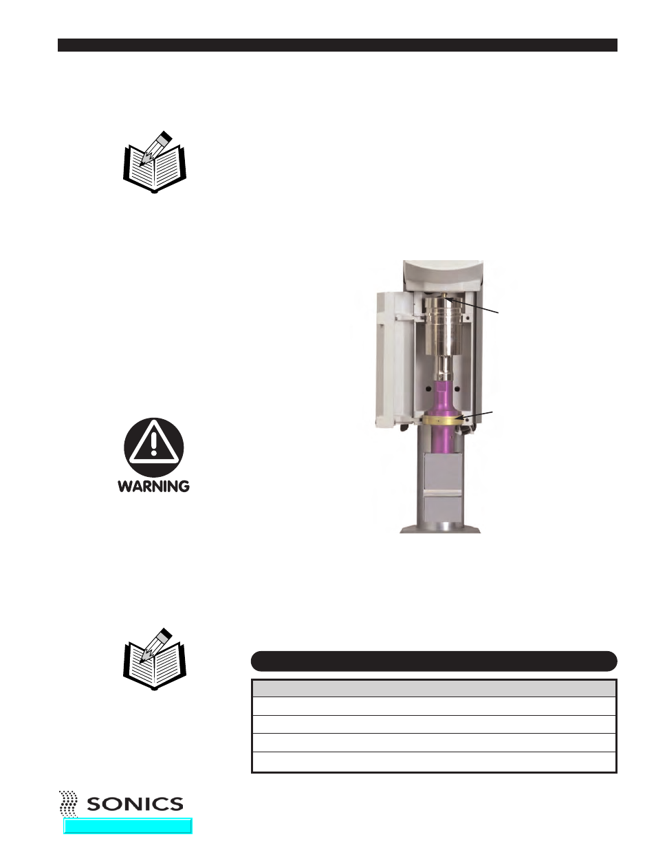
6. Place the converter / booster / horn assembly (stack) in the housing with
the horn facing down. Fit the male brass button on the top of the converter
into the female brass fitting in the bottom of the contact block assembly
housing, and gently push the assembly up and in so that the booster
mounting ring rests on the lower support ridge.
7. Close the converter housing door and tighten (turn clockwise) the two
socket head cap screws until they are snug. Do not tighten the horn to the
booster using the door as a clamp. Hand-forcing the horn on and off in this
manner can twist wires in the converter and cause a failure. If the horn is
not correctly oriented to the part, re-position the stack assembly by
loosening the converter housing cover and rotating the stack.
RECOMMENDED TORQUE REQUIREMENTS
NOTE: If you do not close
the housing door once the
assembly is in place, the
assembly can fall out.
Never tighten the horn to
the booster using the
housing door as the upper
wrench as this may cause
damage to the booster
and/or converter.
CONVERTER / BOOSTER /
HORN ASSEMBLY
NOTE: When performing
any of the operations
described on this page and
pages 16-17, DO NOT turn
on the power supply.
BRASS BUTTON
BOOSTER RING
Go To Top Of Document