Slant/Fin HWT-120 User Manual
Page 8
8
INDIRECT FIRED WATER TANK
IV PIPING DIAGRAM AND INSTRUCTIONS
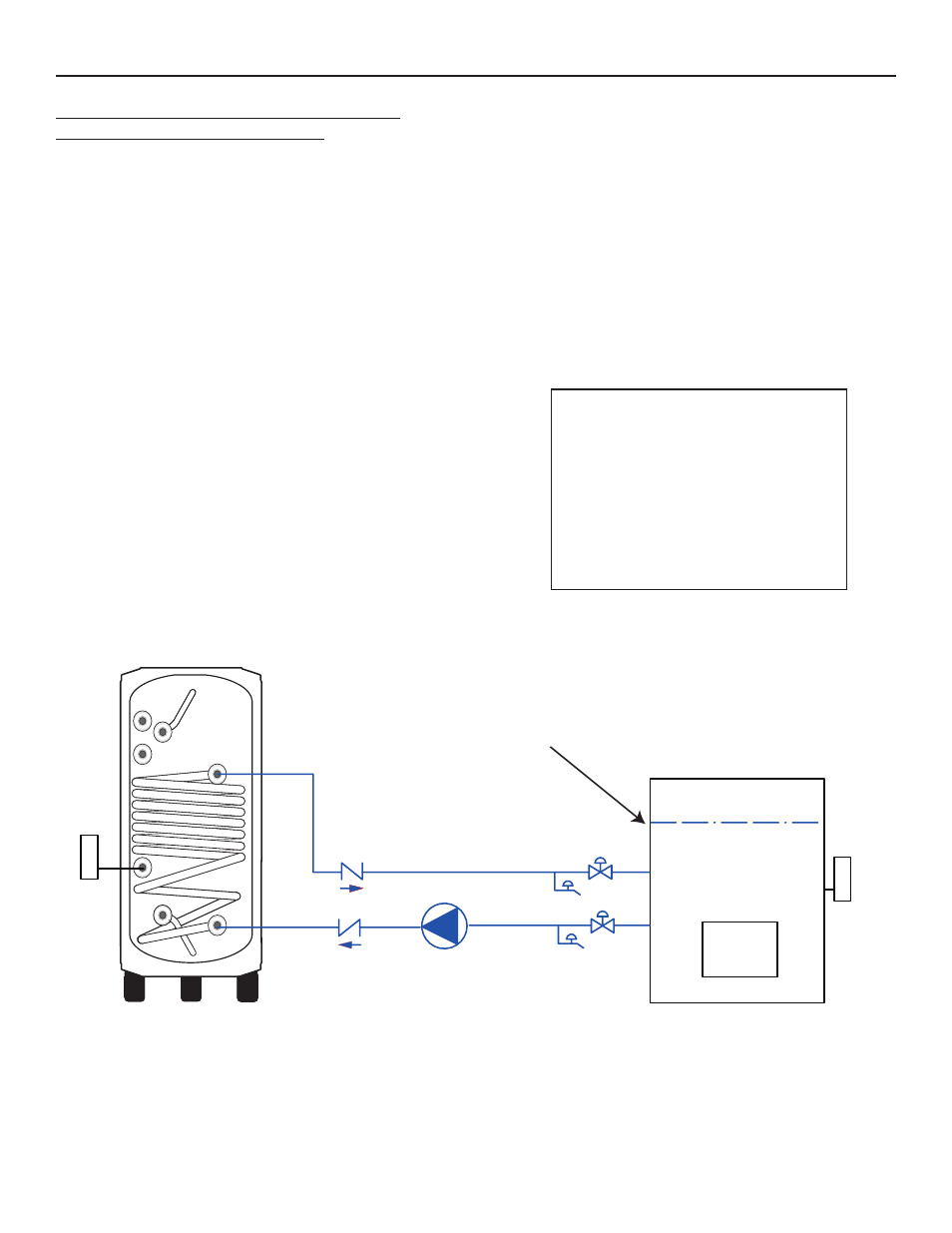
FOR USE WITH A STEAM BOILER
INSTALLATION:
Install valves B and C a minimum of 6" below
water line G. Keep valves as close to the boiler
as possible. Install boilers drains D and E as close
as possible to valves B and C.
FILL AND PURGE:
Close valves B and C. Attach a hose from an independent
water source to boiler drain E. Attach a hose to boiler
drain D leaving open end of hose in an empty bucket or
basin. Open boiler drain E and D and allow water to fill coil
of tank. Continue to allow water to flow until the flow
is free of air. (smooth, non-sputtering flow) Close boiler
drain D and then boiler drain E.
Open valves B and C and observe boiler water level at the
gauge glass making sure that it remains at its original
level. Fill the potable water side of the tank and purge air
from tank by opening a hot water faucet.
When the power is switched on, the tank aquastat will turn
on pump F and when the temperature of the boiler falls
below the set-point, the boiler will fire
A
A
B
C
E
D
F
G
I
H
Water level
STEAM BOILER
A Flow control valve
B Ball or gate valve
C Ball or gate valve
D Boiler drain
E Boiler drain
F Permanently lubricated pump
G Water level
H Tank Aquastat
I Boiler Aquastat
NOTE: When installing the Slant/Fin Indirect Water Heater with a steam boiler, the water flow (direction)
is reversed through the tank coil (heat exchanger). The boiler water enters at the bottom of the coil and
exits from the top of the coil. At no time should live steam be used in the tank coil (heat exchanger).