Warning – Reznor S5BP Unit Installation Manual User Manual
Page 7
7
thermostat Connections
• Thermostat connections should be made in
accordance with the instructions supplied with the
thermostat and the indoor equipment.
• Single stage or two-stage thermostats can be
used with this equipment depending on optional
accessories (i.e. economizer) installed with the unit.
Select a thermostat that operates in conjunction
with the installed accessories. A typical commercial
installation with an air conditioner thermostat and
air handler is shown in Figure 3 (page 13).
• The outdoor unit is designed to operate from a
24 VAC Class II control circuit. The control circuit
wiring must comply with the current provisions of
the NEC (ANSI/NFPA 70) and with applicable local
codes having jurisdiction.
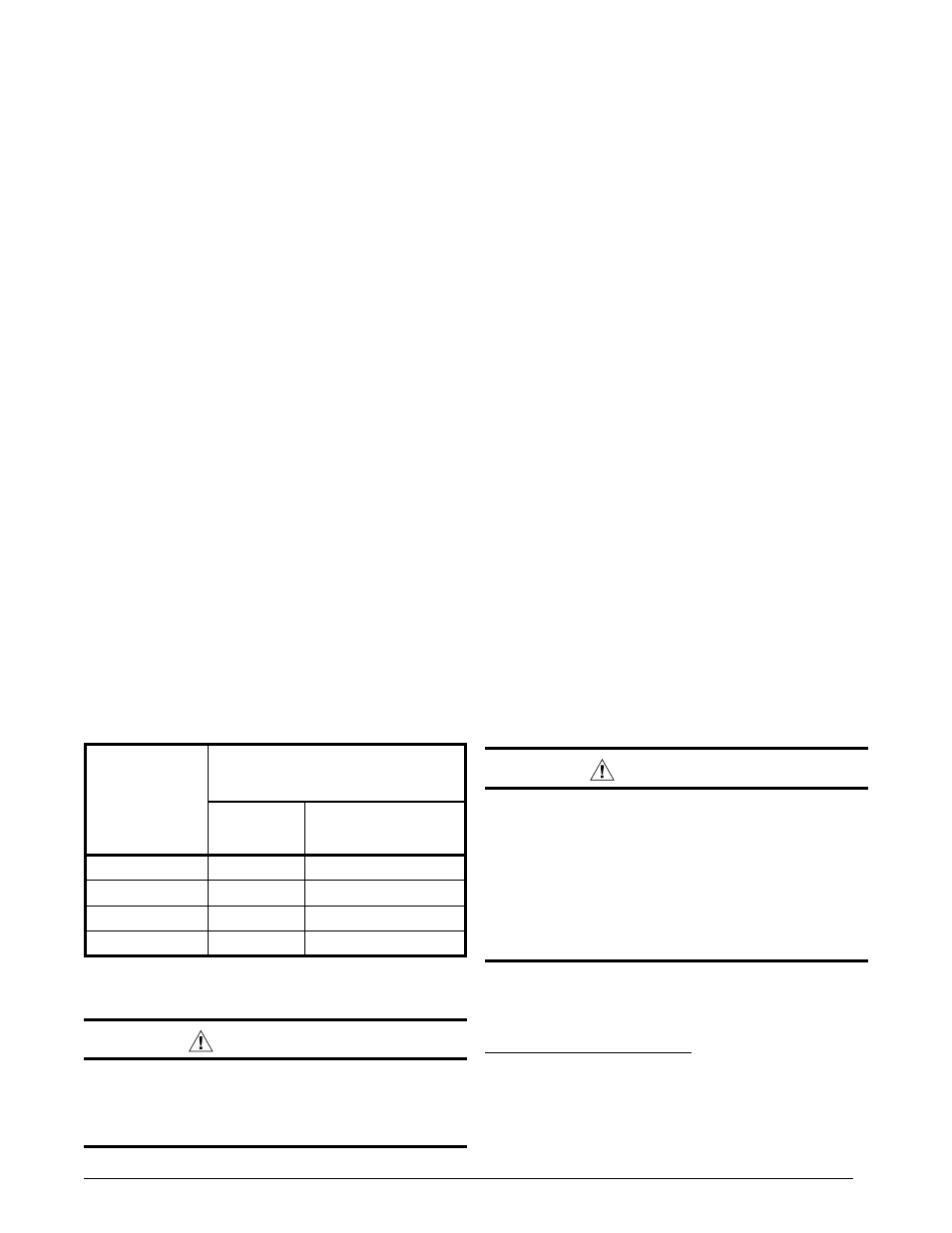
• The low voltage wires must be properly connected to
the units low voltage terminal block. Recommended
wire gauge and wire lengths for typical thermostat
connections are listed in Table 2.
• The thermostat should be mounted about 5 feet
above the floor on an inside wall. DO NOT install
the thermostat on an outside wall or any other
location where its operation may be adversely
affected by radiant heat from fireplaces, sunlight,
or lighting fixtures, and convective heat from warm
air registers or electrical appliances. Refer to the
thermostat manufacturer’s instruction sheet for
detailed mounting and installation information.
table 2. thermostat Wire Gauge
thermostat
Wire Gauge
Recommended t-Stat Wire
length (unit to t-Stat)
2-Wire
(Heating)
5-Wire
(Heating/Cooling)
24
55
25
22
90
45
20
140
70
18
225
110
optional Electric Heater Kits
Optional field-installed electric heater kits are available
in 10 kw through 36 kw heating capacities. Split System
Air conditioners are designed to allow optional auxiliary
electric heat to be field installed as required by the building’s
particular heating load. The options available for each
unit are shown in the heater kit installation instructions.
Install the heater kits as directed by the instructions
supplied with the heater kit. Follow all cautions and
warnings as directed.
This unit must be electrically grounded in accordance
with local codes or, in the absence of local codes, with
the National Electrical Code (ANSI/NFPA 70) or the CSA
C22.1 Electrical Code. Use the grounding lug provided in
the control box for grounding the unit.
The amount of phase imbalance (1.32%) is satisfactory
since the amount is lower than the maximum allowable
2%. Please contact your local electric utility company if
your voltage imbalance is more than 2%.
Grounding
WARnInG:
the unit cabinet must have an uninterrupted or
unbroken electrical ground to minimize personal
injury if an electrical fault should occur. Do not
use gas piping as an electrical ground
!
StARt uP & ADJuStMEntS
Pre-Start Check list
√ Verify the indoor unit is level and allows proper
condensate drainage.
√ Verify the outdoor coil and top of the unit are free
from obstructions and debris, and all equipment
access/control panels are in place.
√ Verify that the duct work is sealed to prevent air
leakage.
√ Verify that the line voltage power leads are securely
connected and the unit is properly grounded.
√ Verify the low voltage wires are securely connected
to the correct leads on the low voltage terminal strip.
√ Verify that the power supply branch circuit overcur-
rent protection is sized properly.
√ Verify that the thermostat is wired correctly.
Start-up Procedures
WARnInG:
this unit is equipped with a crankcase heater.
Allow 24 hours prior to continuing the start up
procedures to allow for heating of the refrigerant
compressor crankcase. Failure to comply may
result in damage and could cause premature
failure of the system. this warning should be
followed at initial start up and any time the
power has been removed for 12 hours or longer.
The thermostat's function mode should be set to OFF and
the fan mode should be set to AUTO. Close all electrical
disconnects to energize the system.
Air Circulation - Indoor Blower
1. Set the thermostat system mode on OFF and the fan
mode to ON.
2. Verify the blower runs continuously. Check the air
delivery at the supply registers and adjust register
openings for balanced air distribution. If insufficient