Reznor S5BP Unit Installation Manual User Manual
Page 6
6
Line Voltage
• A wiring diagram is located on the inside cover of
the electrical box of the outdoor unit. The installer
should become familiar with the wiring diagram
before making any electrical connections to the
outdoor unit.
•
An electrical disconnect must be located within
sight of and readily accessible to the unit. This
switch shall be capable of electrically de-energizing
the outdoor unit.
• Line voltage to the unit should be supplied from
a dedicated branch circuit containing the correct
fuse or circuit breaker for the unit. Incoming field
wiring and minimum size of electrical conductors
and circuit protection must be in compliance with
information listed on the outdoor unit data label.
Any other wiring methods must be acceptable to
authority having jurisdiction.
• The outdoor unit requires both power and control
circuit electrical connections. Refer to the wiring
diagram / schematic for identification and location of
outdoor unit field wiring interfaces. Make all electrical
connections in accordance with all applicable codes
and ordinances. See Figures 2 & 3 (pages 12 & 13).
• Overcurrent protection must be provided at the
branch circuit distribution panel and sized as shown
on the unit rating label and according to applicable
local codes. See the unit rating plate for minimum
circuit ampacity and maximum overcurrent protection
limits.
• Provide power supply for the unit in accordance with
the unit wiring diagram, and the unit rating plate.
Connect the line-voltage leads to the terminals on
the contactor inside the control compartment.
• Use only copper wire for the line voltage power
supply to this unit as listed in Table 1. Use proper
code agency listed conduit and a conduit connector
for connecting the supply wires to the unit. Use of
rain tight conduit is recommended.
CoPPER WIRE SIZE — AWG
(1% Voltage Drop)
Supply Wire length-Feet
Supply Circuit
Ampacity
200
150
100
50
6
8
10
14
15
4
6
8
12
20
4
6
8
10
25
4
4
6
10
30
3
4
6
8
35
3
4
6
8
40
2
3
4
6
45
2
3
4
6
50
2
3
4
6
55
1
2
3
4
60
Wire Size based on N.E.C. for 60° type copper conductors.
table 1. Copper Wire Size
= 1.32%
Example
:
AB = 451V
BC = 460V
AC = 453V
2. Determine the average voltage in the power supply.
3. Determine the maximum deviation:
4. Determine percent of
voltage imbalance by
using the results from
steps 2 & 3 in the
following equation.
max voltage deviation
from average voltage
= 100 x
average voltage
% Voltage Imbalance
6
454
100 x
Example:
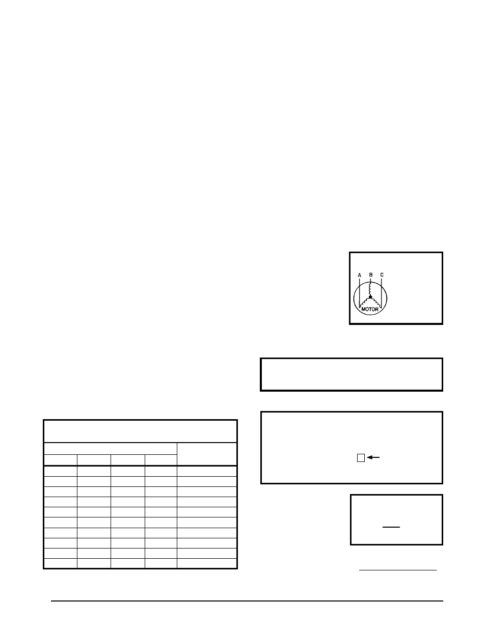
1. M e a s u r e t h e l i n e
voltages of your 3-phase
power supply where it
enters the building and
at a location that will
only be dedicated to the
unit installation (at the
units circuit protection
or disconnect).
Unbalanced 3-Phase Supply Voltage
Voltage unbalance occurs when the voltages of all phases
of a 3-phase power supply are no longer equal. This
unbalance reduces motor efficiency and performance.
Some underlying causes of voltage unbalance may include:
Lack of symmetry in transmission lines, large single-phase
loads, and unbalanced or overloaded transformers. A
motor should never be operated when a phase imbalance
in supply is greater than 2%.
Perform the following steps to determine the percentage
of voltage imbalance:
In this example, the measured line voltages were
451, 460, and 453. The average would be 454 volts
(451 + 460 + 453 = 1,364 / 3 = 454).
Example:
From the values given in step 1, the BC voltage
(460V) is the greatest difference in value from
the average:
460 - 454 = 6
454 - 451 = 3
454 - 453 = 1
Highest Value
• 208/230 Volt units are shipped from the factory wired
for 230 volt operation. For 208V operation, remove
the lead from the transformer terminal marked 240V
and connect it to the terminal marked 208V.
• Optional equipment requiring connection to the
power or control circuits must be wired in strict
accordance of the NEC (ANSI/NFPA 70), applicable
local codes, and the instructions provided with the
equipment.