Warning – Reznor S5BP Unit Installation Manual User Manual
Page 5
5
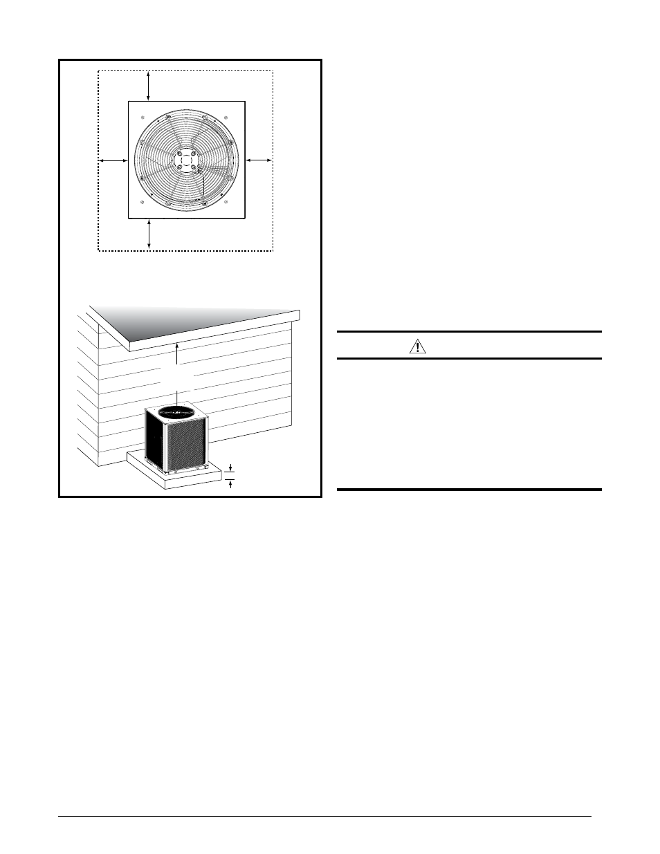
Figure 1. Minimum Clearance Requirements
18"
18"
18"
18"
DO NOT OBSTRUCT
TOP OF UNIT
2”
NOTE: Units require full perimeter clearances. Installer must maintain
18” between two units or single unit and structure.
72”
• When connecting refrigerant linesets together, it is
recommended that dry nitrogen be flowing through
the joints during brazing. This will prevent internal
oxidation and scaling from occurring.
• Refrigerant tubing should be routed in a manner
that minimizes the length of tubing and the number
of bends in the tubing.
• Refrigerant tubing should be supported in a manner
that the tubing will not vibrate or abrade during
system operation.
• Tubing should be kept clean of foreign debris during
installation.
• Every effort should be made by the installer to
ensure that the field installed refrigerant containing
components of the system have been installed
in accordance with these instructions and sound
installation practices to insure reliable system
operation and longevity.
• The maximum recommended interconnecting
refrigerant line lengths are listed in Table 4 (page
13) and the vertical elevation difference between
the indoor and outdoor sections should not exceed
20 feet.
• If precise forming of refrigerant lines is required, a
copper tubing bender is recommended. Avoid sharp
bends and contact of the refrigerant lines with metal
surfaces.
• A filter dryer is provided with the unit and must
be installed in the liquid line of the system. If the
installation replaces a system with a filter dryer
already present in the liquid line, the filter dryer must
be replaced with the one supplied with the unit. The
filter dryer must be installed in strict accordance
with the manufacturer’s installation instructions.
• Optional equipment such as liquid line solenoid
valves, low ambient, etc., should be installed in
strict accordance with the manufacturer’s installation
instructions.
ElECtRICAl WIRInG
WARnInG:
to avoid risk of electrical shock, personal
injury, or death, disconnect all electrical power
to the unit before performing any maintenance
or service. the unit may have more than one
electrical supply.
label all wires prior to disconnection when
servicing the unit. Wiring errors can cause
improper and dangerous operation
• All electrical connections must be in compliance with
all applicable local codes and ordinances, and with
the current revision of the National Electric Code
(ANSI/NFPA 70).
• For Canadian installations the electrical connections
and grounding shall comply with the current
Canadian Electrical Code (CSA C22.1 and/or local
codes).
Pre-Electrical Checklist
√ Verify that the voltage, frequency, and phase of the
supply source match the specifications on the unit
rating plate. Refer to Table 4 (page 11).
√ Verify that the service provided by the utility is
sufficient to handle the additional load imposed
by this equipment. Refer to the unit wiring label for
proper high and low voltage wiring.
√ Verify factory wiring is in accordance with the unit
wiring diagram (Figure 2, page 12). Inspect for loose
connections.
√ Phase balance on 3 phase units must always be
checked. See Unbalanced 3-Phase Supply Voltage
section (page 7).