Warning – Reznor JT4BD Unit Installation Manual User Manual
Page 8
8
Start uP & aDjuStMEntS
Pre-Start check list
√
Verify the unit is level and has sufficient clearances for
unobstructed airflow.
√
Verify the outdoor coil and top of the unit are free from
obstructions and debris, and all equipment access/
control panels are in place.
√
Verify that the line voltage power leads are securely
connected and the unit is properly grounded.
√
Verify that the low voltage wires are securely connected
to the correct leads on the low voltage terminal strip.
√
Verify that the power supply branch circuit overcurrent
protection is sized properly.
√
Verify that the thermostat is wired correctly.
Start-up Procedures
WarnIng:
this unit is equipped with a crankcase heater.
allow 24 hours prior to continuing the start up
procedures to allow for heating of the refrigerant
compressor crankcase. Failure to comply may
result in damage and could cause premature
failure of the system. this warning should be
followed at initial start up and any time the power
has been removed for 12 hours or longer.
Air Circulation - Indoor Blower
1. Set the thermostat system mode on OFF and the fan
mode to ON.
2. Verify the blower runs continuously. Check the air delivery
at the supply registers and adjust register openings for
balanced air distribution. If insufficient air is detected,
examine ductwork for leaks or obstructions.
3. Set the thermostat fan mode to AUTO and verify the
blower stops running.
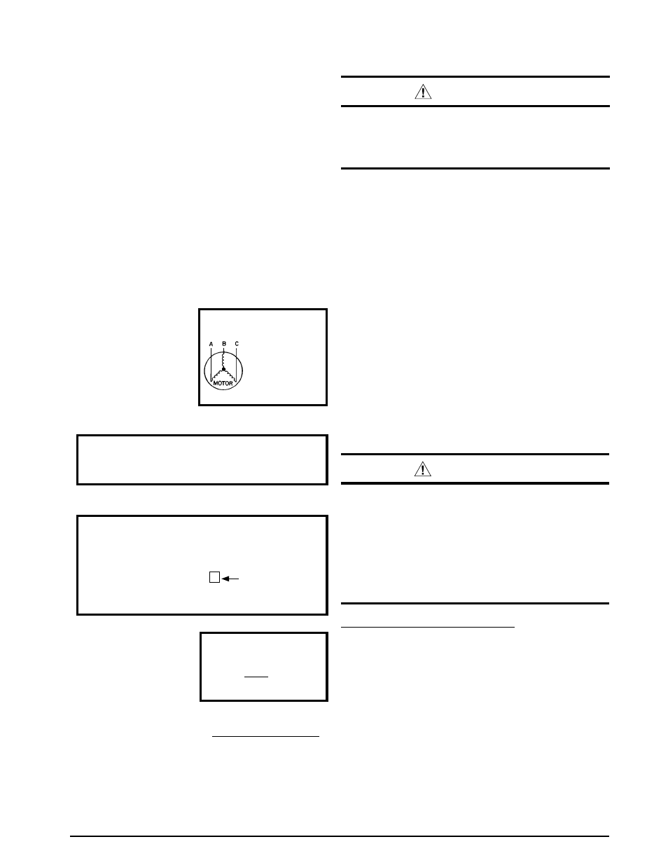
notE: On 3-phase air handler models only - If blower
is spinning opposite of arrow direction, shut off the main
power to the unit and switch any two field wires at the
disconnect. Do not alter unit wiring.
Example
:
AB = 451V
BC = 460V
AC = 453V
2. Determine the average voltage in the power supply.
3. Determine the maximum deviation:
4. Determine percent of
voltage imbalance by
using the results from
steps 2 & 3 in the following
equation.
max voltage deviation
from average voltage
= 100 x
average voltage
% Voltage Imbalance
= 1.32%
6
454
100 x
Example:
1. Measure the line voltages
of your 3-phase power
supply where it enters the
building and at a location
that will only be dedicated
to the unit installation (at
the units circuit protection
or disconnect).
Unbalanced 3-Phase Supply Voltage
Voltage unbalance occurs when the voltages of all phases
of a 3-phase power supply are no longer equal. This
unbalance reduces motor efficiency and performance.
Some underlying causes of voltage unbalance may include:
Lack of symmetry in transmission lines, large single-phase
loads, and unbalanced or overloaded transformers. A
motor should never be operated when a phase imbalance
in supply is greater than 2%. Perform the following steps
to determine the percentage of voltage imbalance:
In this example, the measured line voltages were
451, 460, and 453. The average would be 454 volts
(451 + 460 + 453 = 1,364 / 3 = 454).
The amount of phase imbalance (1.32%) is satisfactory
since the amount is lower than the maximum allowable
2%. Please contact your local electric utility company if
your voltage imbalance is more than 2%.
Example:
From the values given in step 1, the BC voltage
(460V) is the greatest difference in value from
the average:
460 - 454 = 6
454 - 451 = 3
454 - 453 = 1
Highest Value
grounding
WarnIng:
the unit cabinet must have an uninterrupted or
unbroken electrical ground to minimize personal
injury if an electrical fault should occur. Do not
use gas piping as an electrical ground!
This unit must be electrically grounded in accordance
with local codes or, in the absence of local codes, with
the National Electrical Code (ANSI/NFPA 70) or the CSA
C22.1 Electrical Code. Use the grounding lug provided in
the control box for grounding the unit.
abnormally loud noise, immediately switch the outside
power disconnect to the OFF position.
4. Switch any two of the three power leads at the power
connections to the unit.
5. SetReturn to the outside power disconnect and swith
it to the ON position.
6. Verify that the compressor is now running properly.