Wiring dia gram, Split system heat pump three phase – Reznor JT4BD Unit Installation Manual User Manual
Page 24
24
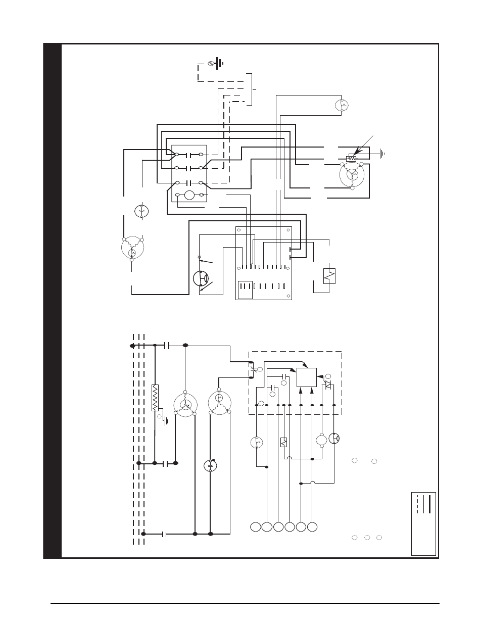
Figure 15. T4BD Wiring Diagram - Three Phase, 208/230V Models
Outdoor Fa
n
Motor
Compressor
Reversing Valve
Solenoid
Defrost
Thermostat
Contactor
C
R
S
Black
Blue
Orange
Black
Black
Red
Yellow
Black
Black
T1
T2
C
Y
O
O
W2
R
R
DFT
DF2
DF1
Defrost Control Board
E
W2
Y
R
C
O
E
Low Voltag
e
Terminals
Red Red
Black
Blue
L1
T2
T1
L3
T3
L2
T3
T2
T1
Capacitor
Yellow
CCH
(If Equipped)
Black
T2 DFT TEST
See Note 6
HPS
Y
ello
w w/
Blac
k Hash
HPS
Grounding
Screw
Grd
(3 Phase) Field Supply
L3
L2
L1
Split System Heat Pump
Three Phase
WIRING DIA
GRAM
NO
TES:
1.
Disconnect all po
wer bef
ore servicing.
2.
For suppl
y connections use copper conductor
s onl
y.
3.
Not suitable on systems that e
xceed 150 v
olts to gr
ound.
4.
For replacement wires use conductor
s suitable f
or 105deg
.
C
5.
For suppl
y wire ampacities and o
ver
current pr
otection,
see unit data label.
6.
Connect to 24 v
ac/40v
a/c
lass 2 cir
cuit
.
See furnace/air handler installation
instructions f
or contr
ol cir
cuit and optional Rela
y/T
rans
fo
rmer Kits
.
1.
Couper le courant
av
ant de faire letretien.
2.
Empl
oy
ez uniquement des conducteu
rs
en cuivre
3.
Ne con
vient pas aux installations de plus de 150
vo
lt a la terre
.
7106870
05/07
FIELD
WIRING
LEGEND:
LO
W
VO
LT
AG
E
HIGH
VO
LT
AG
E
1
2
1
4
3
C
R
S
Compressor
Motor
L1
T1
L2
T2
RVS
R
C
Y
W2
O
E
DFT
R
W2
O
Y
C
T2
T1
DFT
CONTROL
LOGIC
DF2
DF1
CC
Capacitor
T3
T2
T1
CCH (If Equipped
)
Outdoor Fa
n
Motor
L3
T3
Defrost Control Board
Low Voltag
e
Terminals
4W
ith DFT closed and “Y” closed, compressor run time is
accumulated. Opening of DFT during defrost or interval period resets the interval to 0.
Defrost Board Operation:
Closes during defrost. Rating: 1 Amp. Max.
Opens during defrost. Rating: 2 HP. at 230 Vac Max.
Closed when “Y” is on
.
Open when “Y” is off
.
Provide
s“
off” delay time
of 5 min. when “Y” opens.
1
3
2
5
Ground on location provided inside compressor terminal box.
5
¢710687H¤