Comfort alert troubleshooting - continued – Reznor JT4BD Unit Installation Manual User Manual
Page 27
27
coMFort alErt trouBlESHootIng - contInuED
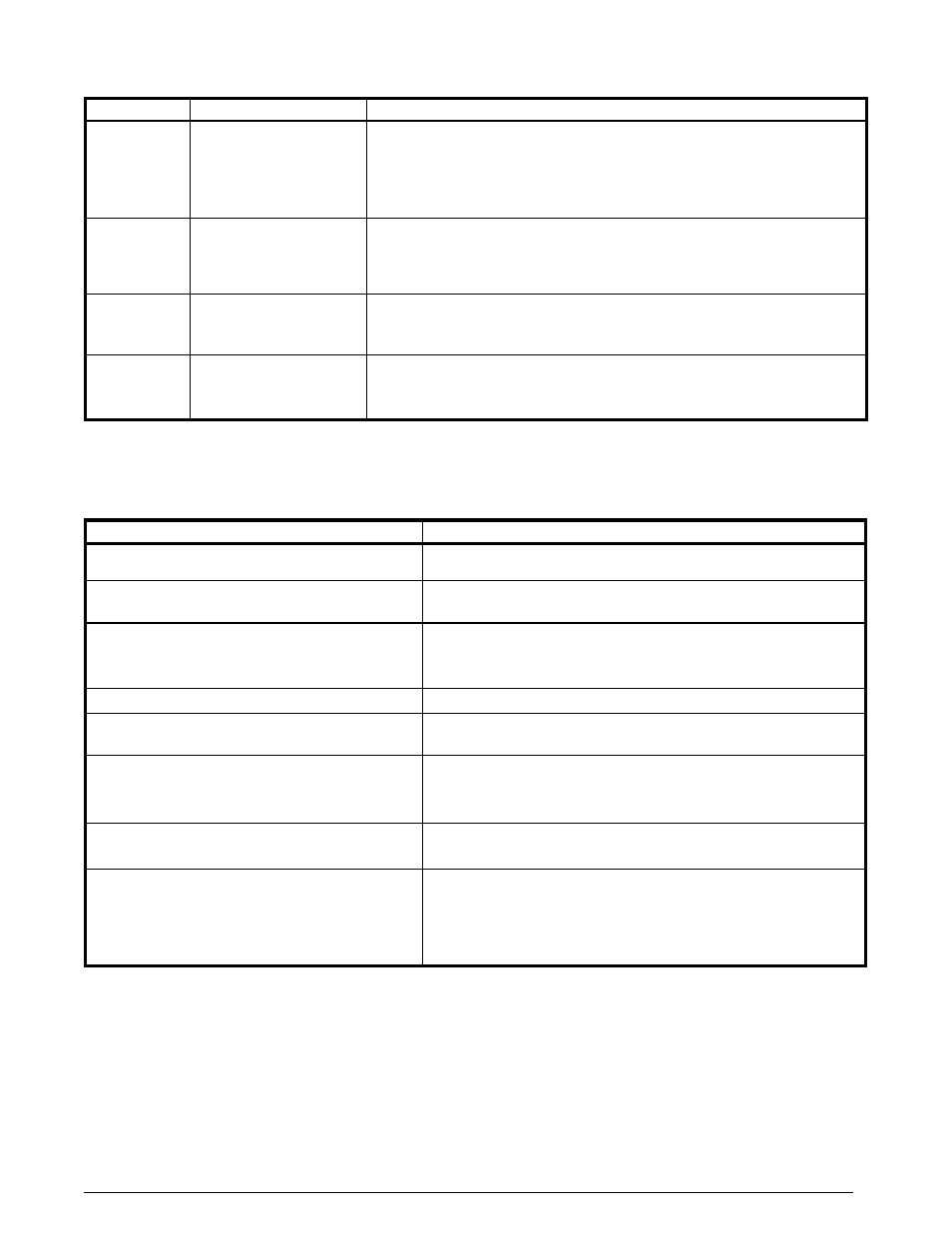
table 17. lED Diagnostics - continued
Status lED Status lED Description
Status lED troubleshooting Information
ALERT
Flash Code 6
(Yellow LED)
Open Start Circuit
Current only in run
circuit
• Run capacitor has failed
• Open circuit in compressor start wiring or connections
— Check wiring and connectors between supply and the compressor S
terminal
• Compressor start winding is damaged
— Check compressor motor winding resistance
ALERT
Flash Code 7
(Yellow LED)
Open run circuit
Current only in start
circuit
• Open circuit in compressor run wiring or connections
— Check wiring and connectors between supply and the compressor r
terminal
• Compressor run winding is damaged
— Check compressor motor winding resistance
ALERT
Flash Code 8
(Yellow LED)
Welded Contactor
Compressor always runs
• Compressor contactor has failed closed
• Thermostat demand signal not connected to module
ALERT
Flash Code 9
(Yellow LED)
Low Voltage
Control circuit < 17VAC
• Control circuit transformer is overloaded
• Low line voltage (contact utility if voltage at disconnect is low)
• Check wiring connections
* Flash code number corresponds to a number of LED flashes, followed by a pause and then repeated. Trip and alert LED’s
flashing at same time means control circuit voltage is too low for operation.
table 18. Module Wiring troubleshooting
Miswired Module Indication
recommended troubleshooting action
Green LED is not on, module does not power up
• Determine if both
r & c module terminals are connected.
• Verify voltage is present at module’s
r & c terminals.
Green LED intermittent, module powers up only when
compressor runs
• Determine if
r & Y terminals are wired in reverse.
• Verify modules R & C terminals have a constant source.
Trip LED is on, but system and compressor check OK
• Verify
Y terminal is connected to 24VAC at contactor coil.
• Verify voltage at contactor coil falls below 0.5VAC when off.
• Verify 24VAC is present across
Y & c when thermostat demand signal is
preset. If not, r & c are reversed wired.
TRIP LED & ALERT LED flashing together
• Verify
r & c terminals are supplied with 19 - 28VAC.
ALERT Flash CODE 3 displayed incorrectly
(Compressor short cycling)
• Verify
Y terminal is connected to 24VAC at contactor coil.
• Verify voltage at contactor coil falls below 0.5VAC when off.
ALERT Flash Code 5, 6, or 7 displayed incorrectly
(Open Circuit, Open Start Circuit or Open Run Circuit)
• Verify the compressor run and start wires are routed through the module’s
current sensing holes.
• Verify the
Y terminal is connected to 24VAC at contactor coil.
• Verify voltage at contactor coil falls below 0.5VAC when off.
ALERT Flash Code 6 (Open Start Circuit) displayed for
Code 7 (Open Run Circuit) or vice-versa
• Verify the compressor run and start wires are routed through the correct
module sensing holes.
ALERT Flash Code 8 displayed incorrectly (Welded
Contactor)
• Determine if module’s
Y terminal is connected.
• Verify
Y terminal is connected to 24VAC at contactor coil.
• Verify 24VAC is present across
Y & c when thermostat demand signal is
present. If not, r & c are reversed wired.
• Verify voltage at contactor coil falls below 0.5VAC when off.
• Review Thermostat Demand Wiring (page 10) for
Y & c wiring.