Wiring dia gram, Single phase – Reznor JT4BD Unit Installation Manual User Manual
Page 23
23
Outdoor
F
an Motor
CC
C
H
F
Dual
Capacitor
(Single Phase)
Field Supp
ly
L1
Gr
d
L2
Gr
ounding
Scre
w
C
S
R
C
Y
Comf
or
t
Aler
t
T1
T2
L1
L2
LPS
HPS
Used in R410a Models Onl
y
Contactor
R
Star
t
Capacitor*
Star
t Rela
y*
5
2
Blac
k
hti
w
w
oll
e
Y
h
s
a
H
k
c
al
B
Comp
Orang
e
Lo
w
Vo
ltag
e
Te
rminal
s
See
Note 6
Red
Red
Defr
ost
Thermosta
t
T2
DFT
TEST
T1
T2
C
Y
O
W2
R
DFT
E
C
Y
O
W2
R
E
DF1
DF
2
Blac
k
Blac
k
Re
ve
rs
ing
Va
lv
e
Solenoid
Ye
ll
ow
CC
w
oll
e
Y
Black
Blue
Blac
k
Defr
ost Cont
ro
l Boar
d
Ye
llo
w
1
CCH
Yellow
L
L
Select
Models
On
ly
Bla
ck
Blue
Blac
k
R
C
S
Bla
ck
Blac
k
Ye
ll
ow
Bla
ck
Ye
ll
ow
Red
WIRING DIA
GRAM
710533E
(Replaces 710533D)
06/10
Status LED
Status LED Description
Green "POWER"
Module has power
Red "TRIP"
Thermostat demand signal Y is present,
but the compressor is not running
Yellow "ALERT" Flash Code 1
Long Run Time
Compressor is running extremely long
run cycle
Yellow "ALERT" Flash Code 2
System Pressure Trip
Discharge or suction pressure out of
limits or compressor overloaded
Yellow "ALERT" Flash Code 3
Short Cycling
Compressor is running only briefly
Yellow "ALERT" Flash Code 4
Locked Rotor
Yellow "ALERT" Flash Code 5
Open Circuit
Yellow "ALERT" Flash Code 6
Open Start Circuit
Current only in run circuit
Yellow "ALERT" Flash Code 7
Open Run Circuit
Current only in start circuit
Yellow "ALERT" Flash Code 8
Welded Contactor
Compressor always runs
Yellow "ALERT" Flash Code 9
Low Voltage
Control circuit < 17 VAC
CCH
1.
Disconnect all po
wer bef
ore servicing.
2.
For supp
ly
connections use copper conductor
s onl
y.
3.
Not suitable on systems that e
xceed 150 v
olts to gr
ound.
4.
For replacement wires use conductor
s suitable
fo
r 105° C.
5.
For ampacities and
ov
er
current pr
otection,
see unit rating plate
.
6.
Connect to 24 v
ac/40v
a/c
lass 2 cir
cuit.
See furnace/air handler installation
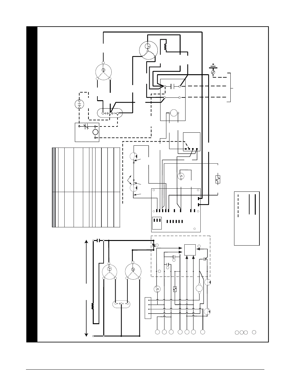
Single Phase
Split System Heat Pump (Outdoor Section)
Legend
Field
Wiring
Fa
ctory
Wiring:
Lo
w
Vo
ltage
High
Vo
ltage
NO
TES:
1.
Couper le courant
av
ant de faire letretien.
2.
Empl
oy
ez uniquement des conducteur
s en cuivr
e.
3.
Ne con
vient pas aux installations de plus de 150 v
olt a la terre
.
instructions f
or contr
ol cir
cuit and optional rela
y/transf
ormer kits
.
1
2
3
4
Dual
Capacito
r
H
C
F
Compressor
Contact
s
Compressor
Outdoor F
an Motor
R
C
S
L1
T1
L2
T2
Lo
w
Vo
ltag
e
Te
rminal
s
E
Defr
ost
Cont
ro
l
Boar
d
DF
T
Cont
ro
l
Logic
DF
1
DF
2
DF
T
1
2
3
4
1
R
W2
O
Y
C
T2
T1
R
W2
O
Y
C
RV
S
CC - Contactor Coi
l
CCH - Crankcase Heater
DFT - Defr
ost
Thermostat
HPS - High Pressure Switc
h
LPS - Lo
w Pressure Swit
ch
RV
S - Re
ve
rs
ing
Va
lve Solenoi
d
* - Har
d Star
t Kit Field Installed
Closing during defr
ost.
Rating:
1 Amp
. Max.
Opens during defr
o
st.
Rating:
2 HP at 230
V
ac Max.
Closed when "Y" is on
. Open when "Y" is of
f.
Pr
ov
ides "off" dela
y time of 5 min
. when "Y" opens
.
With DFT
cl
osed and "Y" c
losed
, compressor run
time is accum
ulated.
Opening of DFT durin
g
defr
ost or interv
al period resets the inter
va
l to 0.
Defr
ost Boar
d Operation:
HPS
LPS
2
08/230V
Y
C
R
L
Comf
or
t
Aler
t
CC
Select
Models Onl
y
L
R
C
S
¢710533z¤
Figure 14. t4BD Wiring Diagram - Single Phase Models with comfort alert