Sample current draw spreadsheet – Potter Fire Alarm Systems User Manual
Page 30
28
Fire Alarm Training • 8700055 • Rev F • 4/10
Current Requirement:
Standby (A) ______ Amps. Alarm (B)______ Amps.
Battery Capacity Requirement:
([Standby (A) ______ ] X [(24 or 60 Hours) ___ ]) + ([Alarm (B) ______ ] X [%Alarm in Hr.] _____) = (C)
______AH
X 1.20
Total Standby Power ______ AH
* Assuming three Initiating Circuits in alarm.
% Use 0.084 for five minutes of alarm or 0.5 for thirty minutes of alarm as a multiplier figure.
See Appendix C, for other available smoke detectors.
Electronic version available at www.pottersignal.com
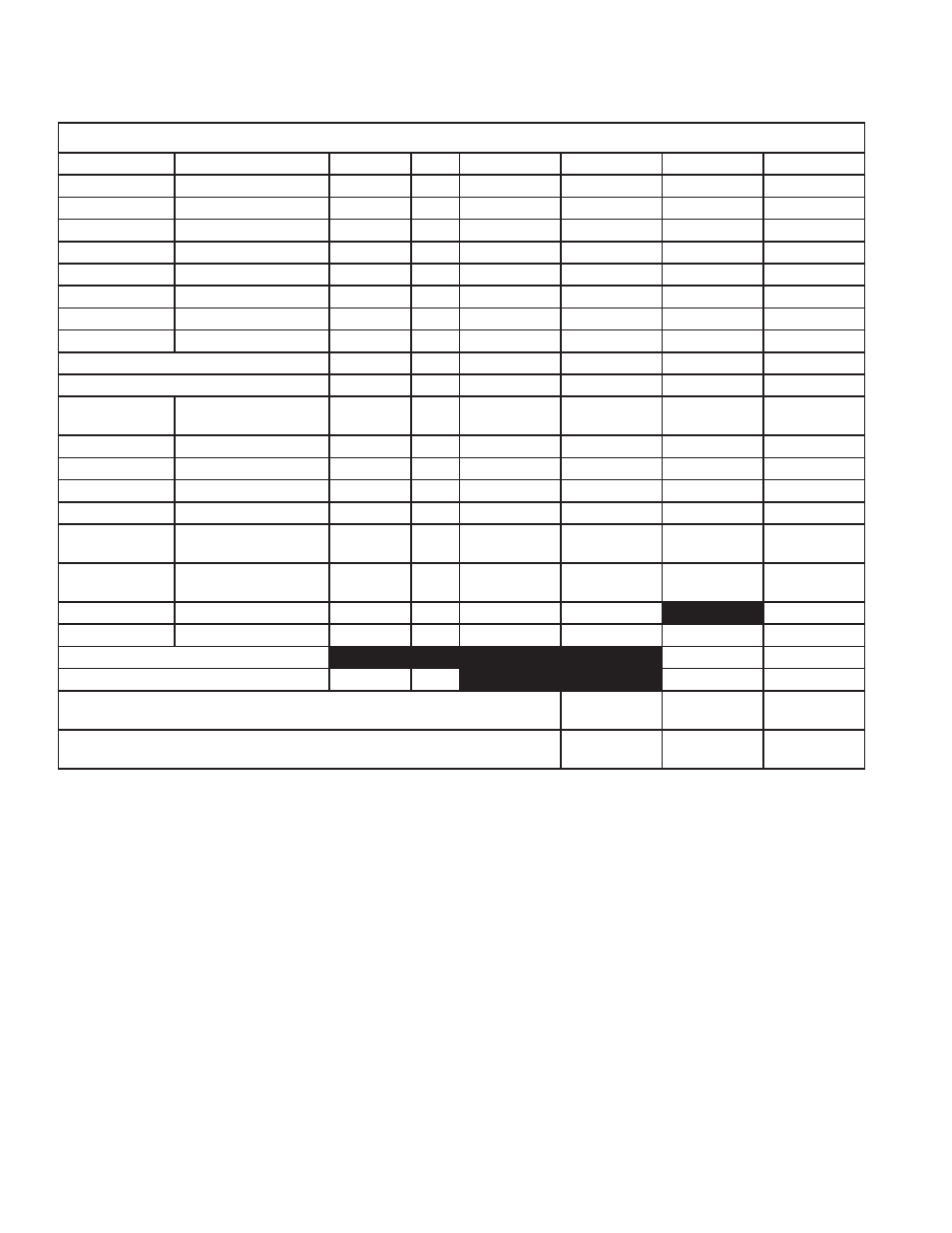
Sample Current Draw Spreadsheet
Power Requirements (All Currents are in Miliamperes)
Model Number
Description
Quantity
Standby
Total Standby
Alarm
Total Alarm
PFC-9000
Main chassis (12 amp)
1
x
230
= 230
380
= 380
SLA-127P
Single loop adder
x
35
=
50
=
DLA-254P
Dual loop adder
x
35
=
50
=
ZA-9008
4 zone NAC card
x
80
=
100
=
IDC-9004
4 zone NAC card
x
35
=
150
=
ARM-9008
8 relay circuit module
x
25
=
150
=
UDACT-9100
Dialer module
x
45
=
120
=
PR-5000
City tie module
x
35
=
300
=
2 Wire smoke detectors
x
=
*0.090
=
4 Wire smoke detectors
x
=
=
APS
Photoelectric smoke
sensor
x
.390
=
.390
=
AHD
Heat sensor
x
.350
=
.350
=
AIS
Ionization smoke sensor
x
.350
=
.350
=
ADSD-P
Duct detector
x
2
=
8
=
ADSD-R
Duct detector with relay
x
10
=
55
=
FRCM-2/-4
Fast response contact
module
x
.550
=
30
=
SOM-4
Supervised output
module
x
.220
=
300
=
PSCI
Short circuit isolator
x
.270
=
= 10
DRM
Dual realy module
x
.150
=
150
=
Alarm LED current for analog devices
135
= 135
Signal load (bells, horns, strobes)
x
=
Auxiliary power supply for remote annunciators. Add 150mA for each RA-LCD and
RA-LED32. Add 50mA for each RA-LED48 annunciator.
=
=
Total currents (add above currents) then multiply to convert to Amperes
Standby
x.001
(A)
Alarm
x.001
(B)