Potter Fire Alarm Systems User Manual
Page 26
24
Fire Alarm Training • 8700055 • Rev F • 4/10
Visual Notification
The requirement for visual notification appliances comes from the applicable building code. The Americans with Disabilities Act
(ADA) also requires strobes in certain instances. Strobe requirements of the ADA apply to new construction of or renovations to
portions of buildings open to the general public. Likewise strobes are required by the ADA in portions of any building accessible
to a hearing impaired person. In commercial facilities, strobes would be located in areas accessible to the public and to occupants
of the facility who may have a hearing disability. Areas such as conference rooms, restrooms, hallways, routes of tours & the
private office of someone with a hearing disability are examples. If no employees have hearing disabilities and the facility is not
open to the public, no strobes would be required. When strobes are required, the installation, operation and location requirements
are the same for ADA and the NFPA. The ADA is enforced through litigation. For more information on the ADA, contact:
http://www.access-board.gov/ada-aba/commrept.htm#702
Candela Information
Visual appliances are installed in one of two orientations, wall mount and ceiling mount. Flashing strobes are listed for a
particular orientation and are required to be installed in that orientation. Wall mount strobes cannot be mounted on ceilings for
visual notification.Most often the strobes are used in a wall mount configuration. These devices may have a split candela rating
depending on the angle in which the viewer is looking at the device. For example, a 15/75-candela strobe has a 15-candela rating
when looking at the device from a 90-degree angle. The same device has a 75-candela rating when looking straight at the device.
Wall mount strobes are required to be mount between 80 and 96 inches from the finished floor level. The spacing requirements
for the visual devices are based on the tables in NFPA 72. The spacing is based on the square area covered by a single device. The
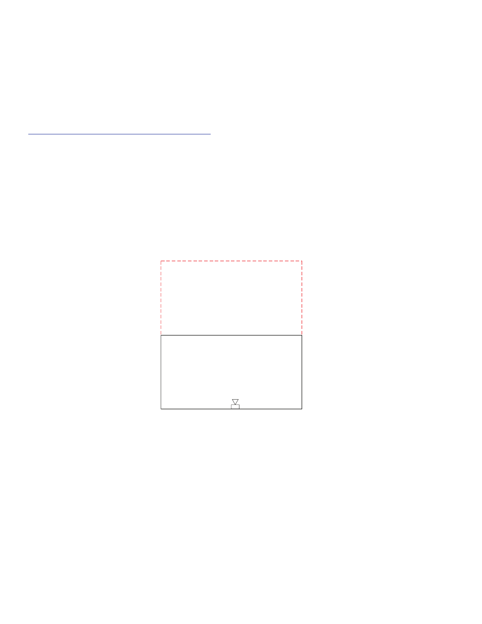
area of notification is determined when the device that entirely covers that area is used. In the example below, the room is 40 feet
wide by 20 feet deep. The room would be required to have a minimum of a single 60-candela strobe or two 30-candela strobes on
the shorter sidewalls opposite of each other.
40 FEET
20 FEET
DWG# 55-12
40 x 40 feet Strobe Requirement
When visual devices are mounted on the walls, the strobe configuration is either a single device per area, two devices per area, or
four devices per area. NFPA 72 has tables that define the minimum required light output. Generally, the largest room area covered
by a single wall mounted device is 70 feet by 70 feet.
Ceiling mounted visual devices are available as multiple candela rated. These strobes are a specific candela but have various
settings depending on the minimum required light output. In addition to the room size, the installer must be cognizant of the
ceiling height when installing ceiling mounted strobes. The maximum ceiling height of any ceiling mounted strobe is 30 feet. If
the ceiling height exceeds 30 feet, the visual devices must be suspended or wall mount strobes must be used. The maximum room
area covered by a ceiling mounted strobe is 50 feet by 50 feet. In addition, the strobe must be mounted in the center of the room
to achieve the light levels as specified in the tables in NFPA 72. If the strobe is not mounted in the center of the room, the distance
from the strobe to the farthest wall is measured, then doubled to determine the room size for the strobe to be used. In the example
below, the strobe is set off center by five feet. Therefore, the farthest wall is 15 feet, that doubled is 30 feet so the strobe must be
at least that which would be used in a 30 feet x 30 feet room.
The light intensity of a strobe device is measured in candela (cd). The strobe devices listed for evacuation have specific light
output requirements that must be complied with for the listing. Power is applied to these devices and the light output is measured
to ensure the proper light output. The minimum light directly in front of the device is 15 cd. Manufacturers design the devices
with various options and light output settings. For example the Potter SH-1224 has six selectable settings of 15, 35, 60, 75, 90 or
110 cd. These various settings each have a specific use depending on the room size and number of visual devices per room.