Carrier 19XL User Manual
Page 97
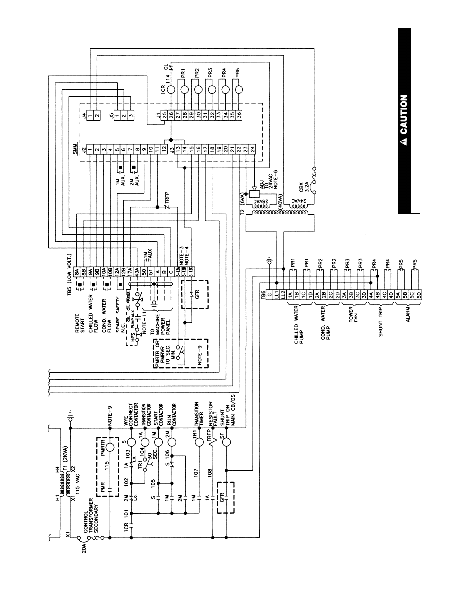
NOTES:
1.
Contactors
2M
and
S
are
mechanically
interlocked.
2.
T
ransition
resistor
fault
protector
(TRFP)
is
preset
to
trip
if
transition
contactor
(1A)
remains
energized
for
longer
than
one
second.
3.
When
optional
phase
loss
reversal
relay
(PMR)
or
phase
loss,
phase
reversal,
overvoltage,
undervoltage
relay
(PMR
VR)
is
not
provided,
terminals
3-13A
and
3-13B
are
jumpered
together
.
4.
When
optional
ground
fault
is
not
provided,
terminals
3-13B
and
3-13C
are
jumpered
together
.
5.
This
oil
pump
circuit
breaker
and
terminal
board
TB7
are
provided
only
on
start-
ers
for
centrifugal
machines.
6.
POT
to
be
adjusted
to
24
v
a
t
rated
line
voltage.
7.
CT4
and
CT5
are
provided
only
when
the
optional
watt
transducer
is
provided.
8.
These
3
wires
to
the
ammeter
switch
are
connected
together
only
when
the
optional
3-phase
ammeter
is
not
provided.
9.
PMR
TR
is
provided
only
if
the
optional
phase
loss
phase
reversal
relay
(PMR)
is
provided.
The
combination
PMR
VR
has
an
internal
time
delay
and
does
not
require
PMR
TR.
10.
Connections
on
the
above
schematic
are
numbered
to
match
the
markings
on
the
control
wires
within
the
starter
.
Wires
entering
terminal
boards
are
marked
with
the
terminal
number
.
1
1
.
Oil
pump
AUX.
contact
not
supplied
on
screw
machines.
NOTE:
Optional
features
are
indicated
by
bold
dotted
boxes.
Yellow
wires
remain
energized
when
main
disconnect
is
of
f.
Fig.
51
—
T
ypical
W
ye-Delta
Unit
Mounted
Starter
W
iring
Schematic
(cont)
97