Physical data – Carrier 19XL User Manual
Page 85
Physical Data —
Tables 12-17 and Fig. 47-51 pro-
vide additional information regarding compressor fits and
clearances, physical and electrical data, and wiring sche-
matics for operator convenience during troubleshooting.
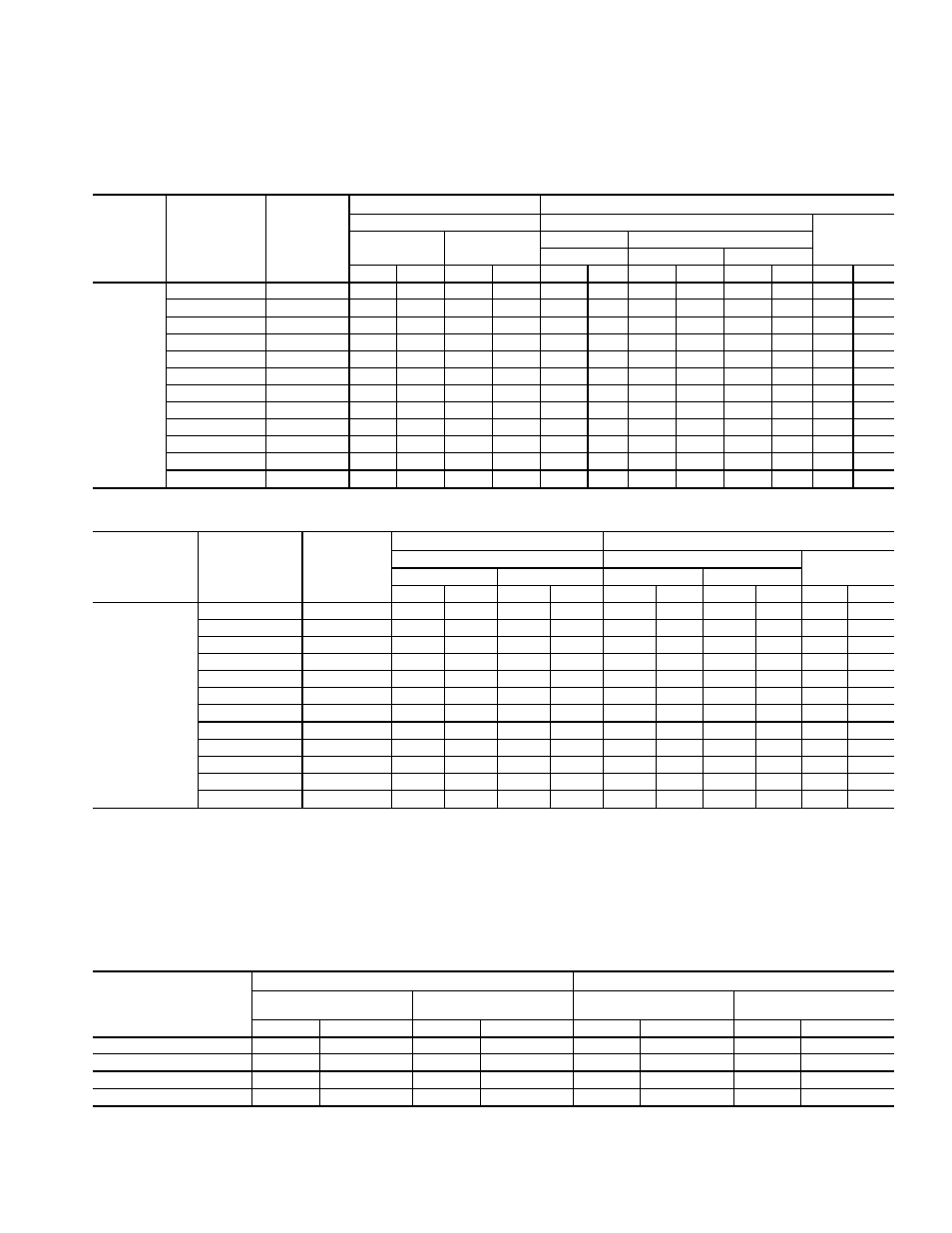
Table 12 — Heat Exchanger Data
COOLER
VESSEL
HEAT
EXCHANGER
CODE
NUMBER
OF TUBES
RIGGING WEIGHTS
VESSEL CHARGE
Dry Wt.
Refrigerant
Volume
of Water
Design I
Design II
Design I
Design II
HCFC-22
HCFC-22
HFC-134a
Lb
Kg
Lb
Kg
Lb
Kg
Lb
Kg
Lb
Kg
Gal
L
COOLER
40
201
5000
2275
5340
2422
1020
463
750
341
550
250
53
201
41
227
5150
2350
5485
2488
1090
494
800
363
600
272
58
220
42
257
5325
2425
5655
2565
1150
522
900
408
650
295
64
242
43
290
5500
2500
5845
2651
1200
544
1000
454
700
318
71
269
50
314
6625
3000
7020
3184
1450
658
1150
522
750
341
79
299
51
355
6850
3100
7255
3291
1500
680
1250
568
850
386
87
329
52
400
7100
3225
7510
3406
1580
717
1400
636
950
431
96
363
53
445
7375
3350
7770
3524
1650
748
1500
681
1000
454
104
394
55
201
—
—
8510
3860
—
—
1410
640
1060
481
104
395
56
227
—
—
8845
4012
—
—
1710
776
1160
527
115
438
57
257
—
—
9205
4175
—
—
2010
913
1260
572
128
486
58
290
—
—
9575
4343
—
—
2210
1003
1410
640
140
531
CONDENSER
VESSEL
HEAT
EXCHANGER
CODE
NUMBER
OF TUBES
RIGGING WEIGHTS
VESSEL CHARGE
Dry Wt.
Refrigerant
Volume
of Water
Design I
Design II
Design I
Design II
Lb
Kg
Lb
Kg
Lb
Kg
Lb
Kg
Gal
L
CONDENSER
40
218
5050
2100
4855
2202
400
181
350
159
56
212
41
246
5200
2350
5010
2272
400
181
350
159
62
235
42
279
5375
2450
5180
2350
400
181
350
159
68
257
43
315
5575
2525
5370
2436
400
181
350
159
75
284
50
347
7050
3200
6750
3062
400
181
350
159
84
318
51
387
7275
3300
6960
3157
400
181
350
159
92
348
52
432
7500
3400
7200
3266
400
181
350
159
101
382
53
484
7775
3525
7475
3391
400
181
350
159
110
416
55
218
—
—
8345
3785
—
—
490
222
112
423
56
246
–
—
8635
3917
—
—
490
222
123
466
57
279
—
—
8980
4073
—
—
490
222
135
513
58
315
—
—
9370
4250
—
—
490
222
149
565
NOTES:
1. Design I chillers are equipped with a float box, and chiller weight is based on a 150 psi (1034 kPa)
waterbox with 2 pass arrangement.
2. Design II chillers are equipped with a linear float, and chiller weight is based on a 300 psi (2068 kPa)
waterbox with 1 pass arrangement.
3. Total refrigerant charge is equal to the cooler charge added to the condenser charge.
Table 13 — Additional Data for Marine Waterboxes*
HEAT EXCHANGER
FRAME, PASS
ENGLISH
SI
Rigging Wt
(lb)
Water Volume
(gal)
Rigging Wt
(kg)
Water Volume
(L)
Cooler
Condenser
Cooler
Condenser
Cooler
Condenser
Cooler
Condenser
FRAME 4, 2 PASS
1115
660
69
51
506
300
261
193
FRAME 4, 1 & 3 PASS
2030
1160
138
101
922
527
524
384
FRAME 5, 2 PASS
1220
935
88
64
554
424
331
243
FRAME 5, 1 & 3 PASS
2240
1705
175
128
1017
774
663
486
*Add to heat exchanger weights and volumes for total weight or volume.
85