Novak XBR Sport Brushless/Brush ESC Profile & Gearing Guide (55-1720P-1) User Manual
Profile selection, Proper gearing, Proper gear selection throttle profile selection
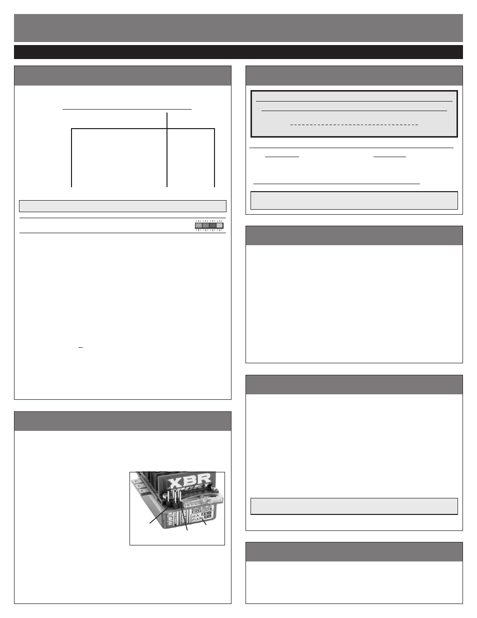
positive
fan pin
negative
fan pin
pin-out
label
The XBR is equipped with
4 user-selectable Throttle Profiles, as shown below.
XBR THROTTLE PROFILES
BRUSHLESS PROFILES
BRUSH-MODE
1
2
3
4
w/Reverse
yes
no
yes
no
Reverse%
100%
n/a
25%
n/a
Programmable
yes
yes
yes
yes
Min.Brake%
0%
0%
0%
0%
Drag Brake
off
off
off
off
Dead Band%
5%
5%
5%
5%
Min.Drive%
1%
1%
1%
1%
NOTE: XBR is factory set to Profile #1
XBR reverts back to Profile #1 & default settings when One-Touch set-up is performed.
selecting brushless profiles
:
all LEDs
With ESC on & connected to a charged battery
(transmitter ON or OFF)
:
1. IF TRANSMITTER IS OFF, DISCONNECT ESC FROM RECEIVER
To avoid possible radio interference, remove the ESC’s input signal harness
from the receiver--
Green LED will stay on to indicate no signal from receiver
.
2. PRESS & HOLD THE ESC’S ONE-TOUCH SET BUTTON
Continue to hold SET button on ESC until all 4 LEDs turns on.
Note: You will continue holding past all the LED programming indicators in
the ESC’s software as shown in the flow chart on back side of this sheet.
3. RELEASE SET BUTTON AS SOON AS ALL 4 LEDs COMES ON
Once released, the 4 status LEDs will flash to indicate what Throttle Profile is
currently selected. The number of times the LEDs flash indicates the Brushless
Throttle Profile selection (1 of 3).
4. QUICK PRESS
(& release)
SET BUTTON TO CHANGE SELECTION
Each press will change to the next consecutive Throttle Profile. (After Profile
3 in Brushless-Mode, the sequence begins again at Profile 1)
Note: there is a time constraint during this selection process.
5. ESC STORES SELECTION & BEGINS TO EXIT PROGRAMMING
If SET button is not pressed for 3 seconds,
ESC stores selected Profile in
memory, exits to neutral & is ready to go. (LEDs turn off in a rolling motion
left to right, then Red LED turns on solid--Green LED will be on if no transmitter
signal present & Blue or Blue & Amber LEDs on if Drag or Min. Brakes above 0%).
Note: ESC reverts to factory default settings & Throttle Profile #1 whenever One-Touch set-up is
performed (reverts to Profile #4 Brush-Mode if no brushless motor sensor harness is connected).
ATTENTION: Correct gearing is essential to getting proper performance from your brushless motor system!
profile selection
&
proper geariNg
proper gear selection
throttle profile selection
5-2007
#55-1720P-1
Motor operating temperature is the ONLY
way to properly set the vehicle gearing
The motor should be 160-175°F MAX at end of run!
Change the gearing to avoid overheating.
General Gearing for 6-Cell Ni-MH or 2-cell Li-Po Use:
MOTOR
PINION
EX8.5/SS8.5/SS5800
1 tooth higher pinion than normally used on 13-17T brush motor
EX10.5/SS10.5/SS4300
1 tooth higher pinion than normally used on 19T brush motor
EX13.5/SS13.5
2-3 teeth higher pinion than normally used on 27T brush motor
If you do not change gearing after switching to brushless, you will be
over-geared and will have slow acceleration & excessive temperatures!
With the broad brushless power band, you can go 1-2 teeth higher pinion than listed above for more top
speed, but remember going higher will produce excessive ESC & motor heating. Check the motor’s operating
temperature after making any gearing adjustments--motors are designed to operate from 160ºF-175ºF.
proFile adjustments
The following parameters are adjustable in the ESC’s software:
MINIMUM BRAKE (1 of 7 settings from 0 to 18%)--The amount of braking applied
with the first pulse of transmitter brake information.
Raising this setting starts the braking at a stronger/higher level.
DRAG BRAKE (1 of 7 settings from 0% {off} to 18%)--The amount of braking applied
while the transmitter is at neutral. Also known as ‘coast’ or ‘auto’ brakes.
Raising this setting makes the motor slow down more without pushing
the transmitter’s trigger into the brake/reverse direction.
(With Drag Brakes on settings 2-10, the Minimum Brake value is the same as the Drag Brake value)
DEAD BAND (1 of 5 settings from 2 to 6%)--The space between Minimum Brake
and Minimum Drive, with neutral in the middle.
Raising this setting will increase the ‘free play’, or distance your trigger
must move before forward drive or braking will begin.
MINIMUM DRIVE (1 of 5 settings from 1 to 12%)--The amount of forward drive
applied with the first pulse of transmitter throttle information.
Raising this setting makes the motor start at a stronger/higher
level so it takes off more aggressively from neutral.
Li-PO cUt-OFF circUitrY
When active (see programming on reverse side to turn ON/OFF), the built-in Smart-
Stop Li-Po Cut-Off Circuitry lets you safely use Lithium Polymer batteries by
cutting off the ESC’s throttle output when a critical safety voltage is reached.
The circuitry constantly monitors the pack voltage. When it gets close to the
critical safety voltage (6.25V) it begins interrupting, or ‘blipping’ the throttle
output as an early warning that the battery’s voltage is getting low and the
throttle output will soon be completely shut off.
When the critical voltage is reached, the throttle output to the motor gets
completely shut down to keep the voltage from dropping further (Red & Green
LEDs will alternately flash & you still have steering control). Re-charge battery after
Smart-Stop circuitry shuts off throttle. Even though the pack’s voltage will
rise (after a short resting period) to a level high enough to run the motor again,
this is not good for Li-Po batteries--
Reaching the critical safety voltage too
many times can damage the cells.
DO NOT CONTINUE TO RUN VEHICLE AFTER
THE SMART-STOP HAS SHUT DOWN THE THROTTLE OUTPUT THE FIRST TIME.
During power-up when the ESC is switched ON, the Amber & Red
LEDs will flash together 3 times to indicate Li-Po Cut-Off is ACTIVE.
With the Li-Po Cut-Off turned ON & using Ni-Cd or Ni-MH cells, the circuitry will shut off the
ESC’s throttle output very early into the run, due to the dfiferent characteristics of these batteries.
mOtOr rOtAtiON SeleCtiOn
The XBR software lets you reverse a brushless motor’s rotation direction (see
reverse side of this sheet to select rotation). This allows installation in vehicles with
counter-rotating drive trains (or opposed transmissions), without compromising
performance. Because the ESC will be operating in its normal forward &
reverse modes, features like Smart Braking continue to operate normally.
AuxilliAry FaN OUtput
The XBR features a set of power output pins for running auxilliary cooling
fans, so you to can add fans to the motor, the ESC, or both, and they will
switch on & off with the ESC’s power switch. These pins output 6.0 VDC (same
as the BEC), so you will get maximum output from your cooling fans without
over-powering them by running directly from the battery pack’s voltage.
The pin-out label located on the front
lower section of the ESC’s case (under
the pins, push button, & LEDs) shows the
polarity of the fan power output pins.
They are the 2 pins on the front edge
of the circuit board--Positive (+) is on
the left, and Negative (–) is on the right.
The set of 3 pins behind them are for the
user-replaceable input signal harness--The
polarity of those is the same: Positive in the
middle, Negative on the right, and the extra
pin on the left is for the input signal.
The Novak 30x30x6mm clear cooling fan
(Novak kit #5648)
is the same one that
comes with the GTB ESC, and not only fits the size of the XBR’s heat sink
perfectly, it also comes with the connector already on it to match the pins
on the XBR. Fans that do not have the proper connector on them will need a
connector
(one end of an old receiver input harness would work well)
put on, or will need to
be soldered to the pins--
Take extra care if attempting to solder to the fan power
output pins--Do not overheat the pins or circuit board, and do not allow any
solder or wire strands to cause a short circuit with other pins.
P5