Step, Connect input harness, Using a receiver battery pack – Novak SLYDR Drift ESC (55-1712-1) User Manual
Page 2: Trouble-shooting guide service procedures, Using battery & motor connectors, One-touch programming, Transmitter adjustments, Mounting esc, Fi gur e 5), Changing wiring sequence @ receive
P3
P2
Blue
LED
Amber
LED
Green
LED
Red
LED
STEP
2-
STEP
1
–
CONNECT INPuT hArNESS
wIrINg SPEEd CONTrOL,
M O T O r & BATTEry
(rEFEr TO FIg. 5)
uSINg A rECEIvEr BATTEry PACk
Steering Channel Works But Motor Will Not Run
• Red status LED blinking when throttle is applied. Check motor sensor harness
connection at ESC (make sure all metal sockets are fully inserted into the connector’s
plastic housing)––check for damaged wires.
• Red status LED on solid & Green LED blinking. Check input signal harness & motor
sensor harness connections at ESC. Check input signal harness wiring sequence &
connection at throttle channel of receiver. Check throttle channel operation with servo.
• Blue & Green status LEDs both blinking. Possible ESC shut-down due to locked
rotor detection––return throttle to neutral position to regain motor control––check
vehicle’s drive train for free operation.
• Blue & Red status LEDs blinking. Possible ESC thermal shut-down––Check gear
ratio & free operation of drive train for possible overloading/ESC is being severely
over-loaded––allow system to cool & return throttle to neutral position to regain motor
control. LEDs will continue to blink until system is cooled down.
• Blue & Amber status LEDs blinking. Possible motor thermal shut-down––Check
gear ratio & free operation of drive train for possible overloading/motor is being over-
loaded––allow system to cool & return throttle to neutral position to regain motor
control. LEDs will continue to blink until system is cooled down.
• Blue & Green (Locked Rotor Detection), Blue & Red (ESC Thermal Shut-Down),
or Blue & Amber (Motor Thermal Shut-Down) status LEDs blinking. ESC may
have shut-down &
ESC’s neutral point is too far off to sense that transmitter throttle
has been returned to neutral––Refer to Steps 4 & 5.
• Red & Green status LEDs toggling. Li-Po Safety Cut-Off voltage reached. Change battery.
• Possible receiver damage––Check operation with a different receiver.
• Possible internal damage––Refer to Service Procedures.
Receiver Glitches/Throttle Stutters During Acceleration
• Receiver or antenna too close to ESC, power wires, battery, or motor.
• Bad connections––Check wiring, connectors, & sensor harness.
• External Power Capacitor damaged/not installed––Replace Power Capacitor.
Motor and Steering Servo Do Not Work
• Check wires, receiver signal harness wiring & color sequence, radio system, crystals,
battery/motor connectors, & battery pack.
• Possible receiver damage––Check operation with a different receiver.
• Possible internal damage––Refer to Service Procedures.
Speed Control Runs Excessively Hot
• Gear ratio too low––Increase gear ratio (see Steps 2 & 3).
Model Runs Slowly/Slow Acceleration
• Gear ratio too high––Reduce gear ratio (see Steps 2 & 3).
• Check battery connectors––Replace if needed.
• Incorrect transmitter/ESC adjustment––Refer to Steps 4 & 5.
• External Power Trans Cap Module damaged/not installed––Replace with #5679.
ESC Is Melted Or Burnt/ESC Runs With Switch Off
• Internal damage––Refer to Service Procedures.
*For more assistance call our Customer Service Department or check our Web site.
TrOuBLE-ShOOTINg guIdE
SErvICE PrOCEdurES
Before sending your speed control or brushless motor system in for
service, review
Trouble-Shooting Guide and all instructions. System
may appear to have failed when other problems exist.
After reviewing instructions, if you feel that your ESC/system requires
service, please obtain the most current product service options and
pricing by the following ways:
WEB SITE:
Print a copy of the PRODUCT SERVICE FORM from the CUSTOMER
SERVICE section of the Web site. Fill out the needed information on this form and
return it with the Novak product that requires servicing.
PHONE/FAX:
If you do not have access to the internet, please contact our customer
service department by phone or fax as listed below.
WARRANTY SERVICE:
For warranty work, you MUST CLAIM WARRANTY
on PRODUCT SERVICE FORM & include a valid cash register receipt with purchase
date and dealer name & phone# on it, or an invoice from previous service. If warranty
provisions have been voided, there will be service charges.
•ESCs returned without a serial number will not be serviced under warranty•
ADDITIONAL NOTES:
• Units that operate normally will have a service charge.
• Dealers/distributors are not authorized to replace Novak products thought to be defective.
• If a hobby dealer returns your brushless system for service, submit a completed PRODUCT
SERVICE FORM to the dealer and make sure it is included with the product.
• Novak does not make any internal electronic components available for sale.
noVaK eLectRonicS, inc.
(949) 833-8873 • FAX (949) 833-1631
Customer Service e-mail: [email protected]
Monday-Friday: 8:00am-5:00pm (PST)
w w w . t e a m n o v a k . c o m
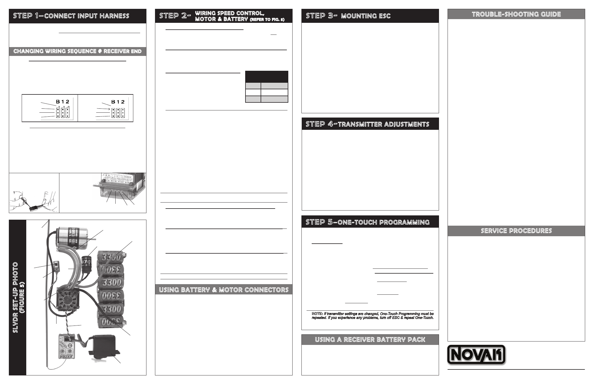
The SLYDR features the industry-standard receiver input connector on a user-
replaceable input harness & works with all major radio brand’s new receivers.
However, some very old receivers must have the wiring sequence in the plastic
3-pin connector housing changed. This is important, because receiver & servo
electronics may be damaged if the sequence is incorrect.
JR • Hitec • Futaba • New KO • Airtronics Z
JR, Hitec, Futaba, new KO, & Airtronics Z receivers do not need input harness
re-wiring. Airtronics Z receivers have blue plastic cases & new KO cases have
tabs on the input harness openings as in
Figure 1.
• Plug one end of the input signal harness into the THROTTLE CHANNEL (#2)
of receiver with the BLACK wire toward the outside edge of receiver case.
• Plug the other end of the input harness onto header pins 4-6 from the left on the
side of the ESC with the BLACK wire going onto the 4th pin from the left.
Note: All pin wiring designations are called out on the label on the ESC’s heat sink.
Old-style KO • Old-style Sanwa/Airtronics
If you have an older KO or Sanwa/Airtronics, you must change the sequence of
the ESC’s input harness wires--Old Sanwa/Airtronics cases are black color & Old
KO cases do not have tab openings, as in
Figure 2 above.
• Using a small flat blade screwdriver, remove the red & black wires from the
plastic housing at the receiver end of the input harness as in Figure 3 below.
• Interchange the red and black wires in the plastic 3-pin connector housing at
the receiver end of the input harness.
• Insert modified end of the harness into the THROTTLE CHANNEL (#2) of receiver
with the RED wire toward the outside edge of receiver case.
• Plug the other end of the input harness onto header pins 4-6 from the left on the
side of the ESC with the BLACK wire going onto the 4th pin from the left.
Mount ESC with power wires away from other electronics & moving parts.
Select a location that allows good airflow through and around the heat sink and
cooling fan--Good air flow allows ESC to run cooler and more efficient!
1. MOUNT ESC IN VEHICLE
using the included double-sided tape.
Be sure the receiver & antenna are mounted as far from ESC, power
wires, battery, & servo as possible--these components all emit RF
noise when the throttle is applied. On graphite or aluminum chassis
vehicles, it may help to place receiver on edge with crystal & antenna
as far above chassis as possible.
Note: Mount the antenna as close to the receiver as possible--trail any excess wire off the
top of the antenna mast (cutting or coiling the excess antenna wire will reduce radio range).
2. SECURE POWER TRANS-CAP MODULE IN VEHICLE
Use the included double-sided tape to mount the Power Trans-Cap
Module to the chassis with the included double-sided tape. Module
can also be tie-wrapped to the power wires or other part of chassis or
shock tower with the included tie-wraps.
3. INSTALL REMOTE POWER PROGRAMMING SWITCH
with the
included double-sided tape where it will be easy to access for turning the
electronics on and off, and also for custom programming (page 4).
With ESC connected to (at least) a receiver & a charged battery pack:
1. TURN ON THE TRANSMITTER’S POWER
2. PRESS & HOLD ESC’S ONE-TOUCH/PROGRAMMING BUTTON
Note: The SLYDR’s One-Touch/Programming button is combined with the
ON/OFF switch on the Remote Power Programming Switch harness.
3. TURN ON THE SPEED CONTROL’S POWER
With transmitter throttle at neutral, and still
pressing the One-Touch button,
slide the ESC’s
ON/OFF switch to ON position.
4. CONTINUE HOLDING BUTTON UNTIL RED LED COMES ON
5. RELEASE ONE-TOUCH BUTTON AS SOON AS LED TURNS RED
6. PULL TRANSMITTER THROTTLE TO FULL-ON POSITION
Hold it there until the
green status LED turns solid green.
Note: Motor will not run during programming even if connected.
7. PUSH TRANSMITTER THROTTLE TO FULL-BRAKES
Hold it there until the
green status LED blinks green.
8. RETURN TRANSMITTER THROTTLE TO NEUTRAL
Red status LED will turn solid red, indicating that speed control is at neutral
and that proper programming has been completed.
NOTE: If transmitter settings are changed, One-Touch Programming must be
repeated. If you experience any problems, turn off ESC & repeat One-Touch.
Whenever One-Touch set-up is performed, ESC automatically reverts to
factory default settings.
1. NO SCHOTTKY OR MOTOR CAPS
DO NOT USE Schottky diodes with the SLYDR--ESC damage will occur
& void the product warranty. External motor capacitors are not required
when operating the SLYDR.
2. FACTORY-INSTALLED POWER TRANS-CAP REQUIRED
The SLYDR comes with a factory-installed Power Trans-Cap Module,
and it MUST be used.
NOTE: If Power Trans-Cap becomes dented or damaged,
ESC failure can occur--replace immediately (#5679). Longer wires on the Power Trans-
Cap Module will decrease performance.
3. CHECK FOR PROPER GEARING
4. SOLDER MOTOR POWER PHASE WIRES TO MOTOR
If you purchased a SLYDR Brushless System, your motor is factory-wired
to a Drift Spec Brushless Motor. Skip to STEP 5.
A. Cut the SLYDR’s BLUE, YELLOW & ORANGE silicone motor power
wires to the desired length, and strip 1/8-1/4” of insulation from the
end of each wire. Tightly twist the exposed strands of wire.
B. Place the ESC’s BLUE Phase ‘A’ motor wire onto motor’s ‘A’ solder
tab & solder. Use a soldering iron to apply heat to exposed wire; begin
adding solder to tip of soldering iron & to wire. Add just enough solder
to form a clean & continuous joint from the plated area of the solder
tab up onto the wire. Use side cutters to trim remaining (now soldered)
wire extending beyond the solder tab (about 1/16” above PCB).
IMPORTANT NOTE:
DO NOT OVERHEAT SOLDER TABS
Prolonged/excessive heating of solder tabs (motor or ESC) will damage PCB.
C. Solder the ESC’s YELLOW Phase ‘B’ motor wire to the motor’s
‘B’ solder tab as described in Step 4B above.
D. Solder the ESC’s ORANGE Phase ‘C’ motor wire to the motor’s
‘C’ solder tab as described in Step 4B above.
Note: Make sure no wire strands have strayed to an adjacent solder tab, this will
result in short-circuiting & severe ESC damage, which will void the warranty.
5. CONNECT MOTOR SENSOR HARNESS TO ESC
Insert the 6-pin connector on the end of the motor’s Teflon sensor
wires into ESC’s sensor harness socket--the connector is keyed and
will only go in, in one direction.
6. SOLDER ESC’S RED WIRE TO BATTERY PACK POSITIVE
(+)
Cut the speed control’s RED silicone power wire to the proper length
so it will reach the battery pack’s POSITIVE (+) terminal. Strip 1/8-
1/4” of insulation from the end of the wire. Tin and solder the exposed
section of wire to battery pack POSITIVE (+).
7. SOLDER ESC’S BLACK WIRE TO BATTERY PACK NEGATIVE
(–)
Cut the speed control’s BLACK silicone power wire to the proper
length so it will reach the battery pack’s NEGATIVE (–) terminal.
Strip 1/8-1/4” of insulation from the end of the wire. Tin and solder
the exposed section of wire to battery pack NEGATIVE (–).
Note: For use with 2S Li-Po packs, Li-Po Cut-Off must be enabled (refer to page 4).
uSINg BATTEry & MOTOr CONNECTOrS
Battery and motor connectors can be used for making your power wire connec-
tions, however they will never have as low of resistance as a good solder joint.
USING BATTERY CONNECTORS: If you are going to use a battery
connector, we recommend Deans
®
Ultra Plug™. Do not use crimp on
types as these cannot handle the high currents found in racing systems.
Please note the following:
• Use connectors that cannot be plugged in backwards--reverse
voltage will damage the SLYDR and void the warranty.
• Use a
female connector on the battery pack to avoid shorting.
• Use a
male connector on the SLYDR’s battery wires.
USING MOTOR CONNECTORS: If you are going to use motor connec-
tors, we recommend the
Novak 3.5mm Low-Loss Connectors (#5731).
Please note the following:
• TAKE EXTRA CARE to prevent motor cross-phase connection as
this will damage ESC and void warranty.
For additional information on connector usage, visit our Web site.
Motor
Turns
Touring Car
Gearing
6.5
7.5
7.5
7
8.5
6.5
Neither the motor (with sintered rotor) nor
the ESC should be hotter than 160 to 175°F
after a 5 min. run. If either temperature is
higher, the gearing should be lowered until
both the ESC and the motor are under this
temperature. The cooler the ESC runs, the
better the performance of the system.
SL
ydr
SET-
u
P P
h
OTO
(FI
gur
E 5)
Trail excess wire of
f top
of antenna mast
(–)
(+)
4 to 6 NiMH or 2S Li-Po cell battery pack
Novak sensor-based
Drift-Spec brushless motor
Red power wire
(battery positive)
Black power wire
(battery negative)
Servo plugged into
steering ch. (#1)
Sensor
Harness
Power Trans-Cap Module
User-replaceable input signal harness (Ch.2)
Blue power wire
(motor phase ‘A’)
Remote Power
Programming Switch
Yellow power wire (motor phase ‘B’)
One-T
ouch
button
Orange power wire (motor phase ‘C’)
Note: For use with 2S Li-Po packs, Li-Po Cut-Of
f must be enabled
(refer to page 4).
ChANgINg wIrINg SEquENCE @ rECEIvE
r ENd
FIGURE 1
FIGURE 2
New KO (with tabs)
Old KO (no tabs)
tabs
no tabs
black
red
red
white
black
white
If you are planning to use an external receiver battery pack to power the
electronics you need to do the following:
1. Plug the external 5 cell (1.2VDC/cell) receiver battery pack into the battery slot
of the receiver.
2. Leave the ESC’s ON/OFF switch in the OFF position & use receiver pack’s ON/
OFF switch to turn system power on and off––Do not use the ESC’s switch.
STEP
5
– ONE-TOuCh PrOgrAMMINg
For proper ESC operation, adjust transmitter as follows:
A. Set HIGH ATV or EPA to maximum setting.
[amount of throw at full throttle]
B. Set LOW ATV, EPA or ATL to maximum setting.
[amount of throw at full brakes]
C. Set EXPONENTIAL to zero setting. [throttle channel linearity]
D. Set THROTTLE CHANNEL REV. SWITCH to either position.
E. Set THROTTLE CHANNEL TRIM to middle setting.
[adjusts neutral position/increases or decreases coast brakes]
F. Set ELECTRONIC TRIGGER THROW ADJUSTMENT to 70% throttle
and
30% brake throw (or 7:3) for Forward & Brake only Profiles, and
50% throttle and 50% brake throw (or 5:5) for Profiles with reverse.
[adjusts trigger throw electronic/digital pistol-grip transmitters]
G. Set MECHANICAL TRIGGER THROW ADJUSTMENT (if radio has it) to position
with
2/3 throttle and 1/3 brake throw for Forward & Brake only Profiles, and
position with
1/2 throttle and 1/2 brake throw for Profiles with Reverse.
[adjusts trigger throw on mechanical/analog pistol-grip transmitters]
•NOT
ALL
TRANSMITTERS HA
VE THESE
ADJUSTMENTS•
STEP
4-
TrANSMITTEr AdjuSTMENTS
STEP
3-
MOuNTINg ESC
FIGURE 3
With a small std
screwdriver, gently lift plastic prong
until wire and metal socket easily
slide out of plastic housing.
FIGURE 4:
LED/Pin-Out Label
Note that LED positions
& what they represent is marked
on the heat sink label, along
with the wiring sequence for
the header pins along the side
for the user-replaceable Remote
Power Programming Switch,
receiver input harness, cooling
fan, & motor sensor harness.