Hv pro esc software flow chart, Throttle parameter settings, Throttle curves – Novak HV Pro Set-Up (55-3221P-2) User Manual
Page 2
P6
PLEASE NOTE: This sheet contains optional Advanced Programming items!
No further adjustments are required.
(But don’t worry, you can always reset factory defaults by performing the One-Touch programming again, so go ahead & experiment—that’s why the programming is in there, right?)
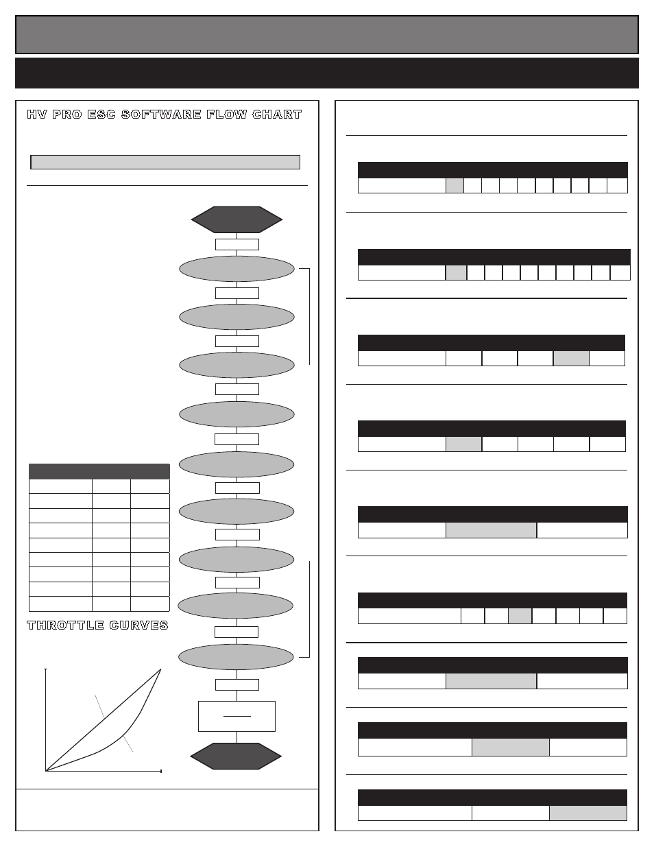
HV PRO ESc SOFTWARE FLOW cHART
The HV Pro ESC features nine parameters
that can be adjusted.
Refer to below flowchart and settings at right. One-Touch programming
should be completed before custom programming.
DEFAULT SETTINGS ARE IN SHADED BOXES @ RIGHT -->
TO CHANGE PARAMETER SETTINGS:
Transmitter can be either ON or OFF:
THROTTLE PARAMETER SETTINgS
(defaults shaded)
1. MINIMUM bRAKE SETTINgS (10)
BLUE LED
Amount of braking applied with first pulse of transmitter throttle information.
--Raising this setting starts the braking at a stronger/higher level
.
Setting
(# of flashes)
1 2 3 4 5 6 7 8 9 10
Minimum Brake (%):
0 3
6
9
12 15 18 21 24 30
2. DRAg bRAKE SETTINgS (10) BLUE & AMBER LEDs
Amount of braking applied while transmitter is at neutral. AKA ‘coast’ brakes.
--Raising this setting makes the motor slow down more, without
pushing the transmitter’s trigger into the brake/reverse direction.
Setting
(# of flashes)
1
2 3 4 5 6 7 8 9 10
Drag Brake (%):
off 3
6
9
12 15 18 21 24 30
3. DEAD bAND SETTINgS (5)
BLUE & GREEN LEDs
Space between Minimum Brake & Minimum Drive, with neutral in middle.
--Raising this setting will increase the ‘free play’, or distance your
trigger must move before forward drive or braking will begin.
Setting
(# of flashes)
1
2
3
4
5
Dead Band (%):
2
3
4
5
6
4. MINIMUM DRIVE SETTINgS (5)
AMBER LED
Amount of forward drive applied with first pulse of transmitter information.
--Raising this setting makes the motor start at a stronger/higher
level so it takes off more aggressively from neutral.
Setting
(# of flashes)
1
2
3
4
5
Minimum Drive (%):
1
3
5
8
12
5. THROTTLE cURVE SELEcTION (3)
GREEN LED
Response curve of drive power applied to motor for a given trigger position.
--Changing this setting changes the throttle response of the motor
and ease of low end drivability--Expo has smoother bottom end.
Setting
(# of flashes)
1
2
Throttle Curve:
Linear
Expo
6. bRAKE FREQUENcY (7)
RED LED
Frequency at which duty cycle information for braking is sent to the motor.
--Raising this setting makes the brake response smoother and
less aggressive.
Setting
(# of flashes)
1
2
3
4
5
6
7
Brake Frequency (kHz):
1
2
3
4
5
7.5
8
7. bRAKES (2)
RED, GREEN, & AMBER LEDs
--Changing this setting activates/deactivates the ESC’s braking.
Setting
(# of flashes)
1
2
Brakes (On/Off):
ON
OFF
8. MOTOR ROTATION (2)
GREEN & AMBER LEDs
--Changing this setting changes direction of motor rotation.
Setting
(# of flashes)
1
2
Motor Rotation (CCW/CW):
CCW
q
CW
p
9. LI-PO cUT-OFF (2)
RED & AMBER LEDs
--Changing this setting enables/disables Auto-Detect LiPo Cut-Off.
Setting
(# of flashes)
1
2
Li-Po Cut-Off (On/Off):
OFF
ON
@NEUTRAL
RED LED on solid
MINIMUM BRAKE
BLUE
press & hold
press & hold
DEAD BAND
BLUE & GREEN
MINIMUM DRIVE
AMBER
press & hold
THROTTLE CURVE
GREEN
LEDs roll off
Exit Programming
@NEUTRAL
RED LED on solid
press & hold
BRAKE FREQUENCY
RED
press & hold
BRAKES
RED / GREEN / AMBER
press & hold
MOTOR ROTATION
GREEN & AMBER
press & hold
LI-PO CUT-OFF
RED & AMBER
press & hold
continue holding ESC
’s SET
button to skip steps here
press & hold
press & hold
DRAG BRAKE
BLUE & AMBER
RESTORINg FAcTORY DEFAULTS:
Every time you perform the One-Touch Set-Up, the ESC is
defaulted to the factory default parameter settings.
1. IF THE TRANSMITTER IS OFF,
D I S C O N N E C T T H E S P E E D
CONTROL FROM RECEIVER
Remove ESC’s input signal harness from
receiver to avoid radio interference.
2. CONNECT ESC TO CHARGED
BATTERY PACKS
3. TURN ESC’s POWER SWITCH ‘ON’
4. WITH ESC AT NEUTRAL PRESS &
HOLD ESC’S SET BUTTON
Release ESC’s SET button once LED
is at desired setting.
To skip a parameter, continue to hold
ESC’s SET button until you reach the
desired parameter.
5. SELECT PARAMETER VALUE
LED flashes to indicate active setting
(see tables at right)
. Quick press & release SET
button to change the value.
6. PRESS & HOLD SET BUTTON TO
STORE SELECTION
When SET button is pressed & held
for about 1 second, new selection is
stored in ESC’s memory--
The status
LEDs scroll across indicating you are exiting
programming & ESC returns to neutral.
Note: there is no time constraint during the selection
of custom parameters while in the programming.
Parameter
Default Custom
Minimum Brake
0%
Drag Brake
off
Dead Band
5%
Minimum Drive
1%
Throttle Curve
Linear
Brake Freq.
3 kHz
Brakes (on/off)
ON
Motor Rotation
CCW q
Li-Po Cut-Off
ON
THROTTLE cURVES
The HV Pro software has 2 throttle
curves as seen below. The ‘Expo’ curve
provides more controllable bottom end.
HV PRO cUSTOM PROgRAMMINg & PROPER gEAR SELEcTION SHEET
Motor Output
Trigger Position
0
100%
100%
Linear
Expo