Synl interrupt, Rgdt and rgmon interrupts – Maxim Integrated 73M1866B/73M1966B Implementers Guide User Manual
Page 26
73M1866B/73M1966B Implementer’s Guide
UG_1x66B_016
26
Rev. 1.3
6.4 SYNL Interrupt
The triggering of the SYNL interrupt indicates that the device has detected a failure in the barrier between
the line and host side device. When found, it can be assumed that there is a problem with the barrier.
This failure is usually a problem with the PLL operation, therefore, the recommended way to deal with this
interrupt is to reset the device PLL.
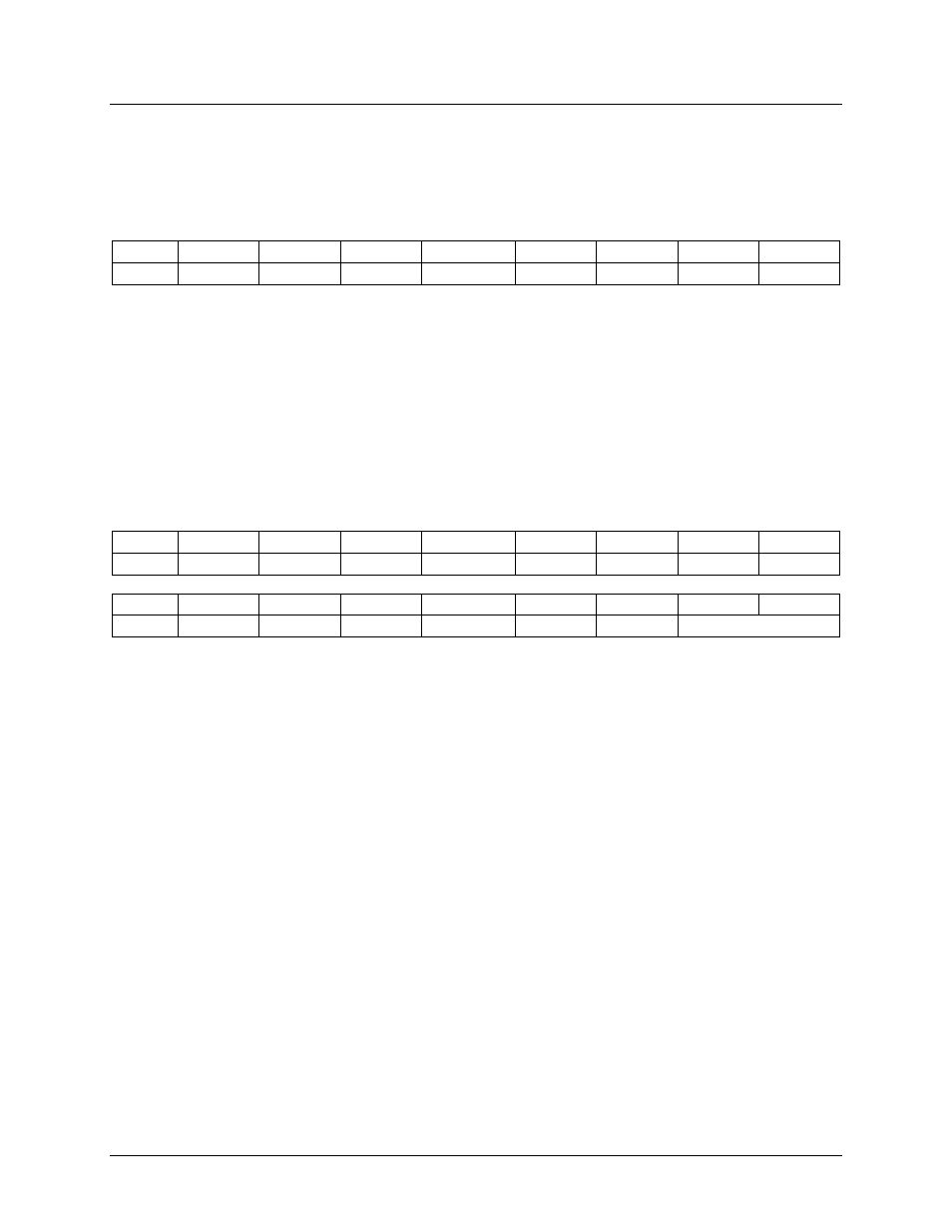
0x05
ENGPIO7 ENGPIO6 ENGPIO5 ENPCLKDT ENAPOL
ENDET
ENSYNL ENRGDT
Write
X
X
X
X
1
X
1
X
Set the RNSYNL bit in Register 0x05 to enable the SYNL interrupt.
Begin
1. If SYNL = 1 (IntSrc = xxxx_xx1x), goto PLL Recovery Process (see
Section 3.1.2 PCLK Clock
Recovery and PLL Lock Detection
End
6.5 RGDT and RGMON Interrupts
The triggering of an RGDT or RGMON interrupt indicates that the device has detected an AC signal on
the line greater than the threshold programmed through the RGTH register.
0x05
ENGPIO7 ENGPIO6 ENGPIO5 ENPCLKDT ENAPOL
ENDET
ENSYNL ENRGDT
Write
X
X
X
X
1
X
X
1
0x0E
FRCVCO
Res
Res
Res
Res
Res
RGTH1
RGTH0
Write
X
X
X
X
X
X
VAL1[1:0]
Set the ENRGDT bit in Register 0x05 to enable the RGDT and RGMON interrupts.
Begin
1. If RGDT = 1 (IntSrc = xxxx_xxx1) or RGMON = 1 (IntSrc = xxxx_1xxx), goto Ring Detection and Line
Polarity Reversal (see
End