4 graphical user interfaces, 1 gui for maxrefdes5, 1 input selection and configuration – Maxim Integrated MAXSANTAFEEVSYS User Manual
Page 8: Graphical user interfaces, Gui for maxrefdes5, Input selection and configuration
MAXSANTAFEEVSYS User Manual
4 Graphical User Interfaces
Before launching the GUI applications, make sure the USB2PMB1 and MAX5216DACLITE boards are
connected to the PC as described in the previous section.
4.1 GUI for MAXREFDES5
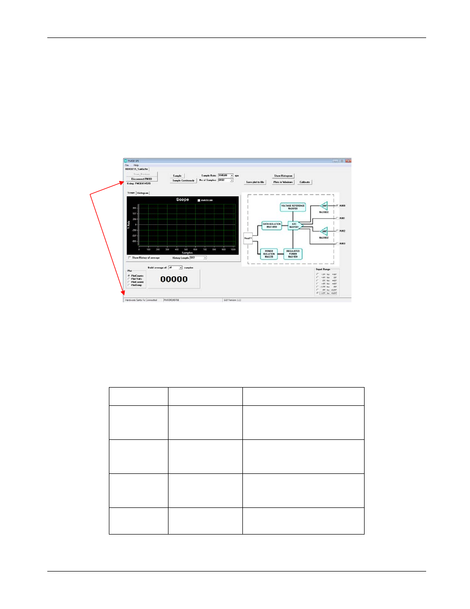
With the USB2PMB1 board connected, run (double-click) the PMOD_SPI.exe GUI application located in the
\MAXREFDES5\ directory. Once the window below appears, press the Connect PMOD button and verify that
the button changes its text to Disconnect PMOD and the status bar at the bottom indicates that the
companion board is connected.
4.1.1 Input Selection and Configuration
While most of the controls in the GUI only adjust the display of information on the screen, there are two
controls that both adjust the GUI display and configure the MAX1301 ADC device used in the MAXREFDES5
design. These controls send a command to the MAX1301 indicating which input to sample and the full scale
range (FSR) for that input. The recommended combinations for the MAXREFDES5 hardware design are
shown in the left two columns of the table below. For reference, the respective channel select bits C[2:0] and
range select bits R[2:0] are also provided along with the full-scale range.
BOARD
INPUT
ADC INPUT
RANGE
MAX1301 INPUT
CONFIGURATION
AIN0
-10V to 10V
-12V to +12V
C[2:0] = 000
R[2:0] = 111
FSR= 6 x V
REF
AIN1
-10V to 10V
-12V to +12V
C[2:0] = 001
R[2:0] = 111
FSR= 6 x V
REF
AIN2
4mA to 20mA
0V to +6V
C[2:0] = 010
R[2:0] = 011
FSR= (3 x V
REF
) / 2
AIN3
0V to 10V
0V to +12V
C[2:0] = 011
R[2:0] = 110
FSR= 3 x V
REF
Rev 0
8