3 maxrefdes5 4-ch afe board, 1 analog signal connections, Maxrefdes5 4-ch afe board – Maxim Integrated MAXSANTAFEEVSYS User Manual
Page 7: Analog signal connections, Maxsantafeevsys user manual
MAXSANTAFEEVSYS User Manual
3.3 MAXREFDES5 4-Ch AFE Board
Connect the MAXREFDES5 board to the USB2PMB1 adaptor. Both connectors should be on the same side of
the PCB when mated together as shown below.
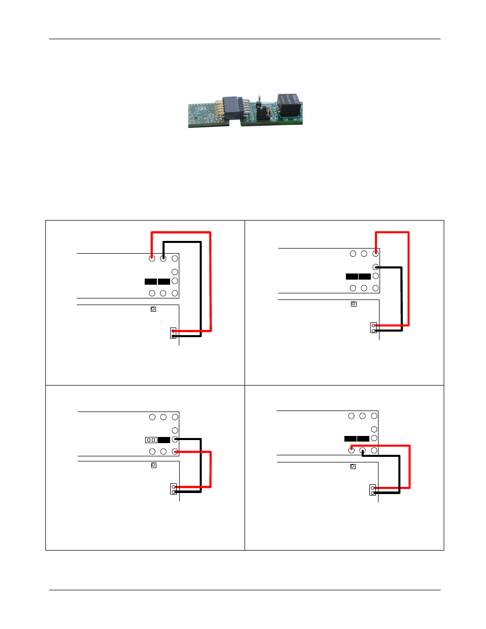
3.3.1 Analog Signal Connections
The following table summarizes the different connection options for the MAXSANTAFEEVSYS kit. Note the
input range of the MAXREFDES5 analog inputs exceeds the output capabilities of the MAX5216DACLITE
board included with the kit.
For testing input AIN2 with a voltage source, a jumper JU2 should be removed to disconnect the on-board
sense resistor. Jumper JU1 on AIN2 is provided for optional connection to a reference ammeter.
J5
OUT
GND
VREF
J4
AIN
0
GND
0
AIN
1
AIN
3
GND
3
AIN
2
GND2
GND1
JU2
JU1
MAXREFDES5
MAX5216DACLITE
AIN
0
GND
0
AIN
1
AIN
3
GND
3
AIN
2
GND2
GND1
JU2
JU1
J5
OUT
GND
VREF
J4
MAXREFDES5
MAX5216DACLITE
Input AIN0
Input AIN1
0V to +3V from DACLITE J5
(or -10V to +10V from alternate source)
0V to +3V from DACLITE J5
(or -10V to +10V from alternate source)
AIN
0
GND
0
AIN
1
AIN
3
GND
3
AIN
2
GND2
GND1
JU2
JU1
J5
OUT
GND
VREF
J4
MAXREFDES5
MAX5216DACLITE
AIN
0
GND
0
AIN
1
AIN
3
GND
3
AIN
2
GND2
GND1
JU2
JU1
J5
OUT
GND
VREF
J4
MAXREFDES5
MAX5216DACLITE
Input AIN2
Input AIN3
+1V to +3V from DACLITE J5 with JU2 removed
(or 4-20mA from current source with JU2 installed)
0V to +3V from DACLITE J5
(or 0V to +10V from alternate source)
Rev 0
7