2 gui for max5216daclite, Gui for max5216daclite – Maxim Integrated MAXSANTAFEEVSYS User Manual
Page 12
MAXSANTAFEEVSYS User Manual
4.2 GUI for MAX5216DACLITE
With the MAX5216DACLITE board connected, click on the MAX5216DACLite shortcut found in the Start
menu. The GUI will automatically connect to the MAX5216DACLITE hardware upon initialization. This section
describes the basic functionality needed to generate test signals for evaluating the MAXREFDES5 design. For
more information on the MAX5216DACLITE GUI, refer to the
For more
information on the MAX5216 or other evaluation kits for the MAX5216, visit
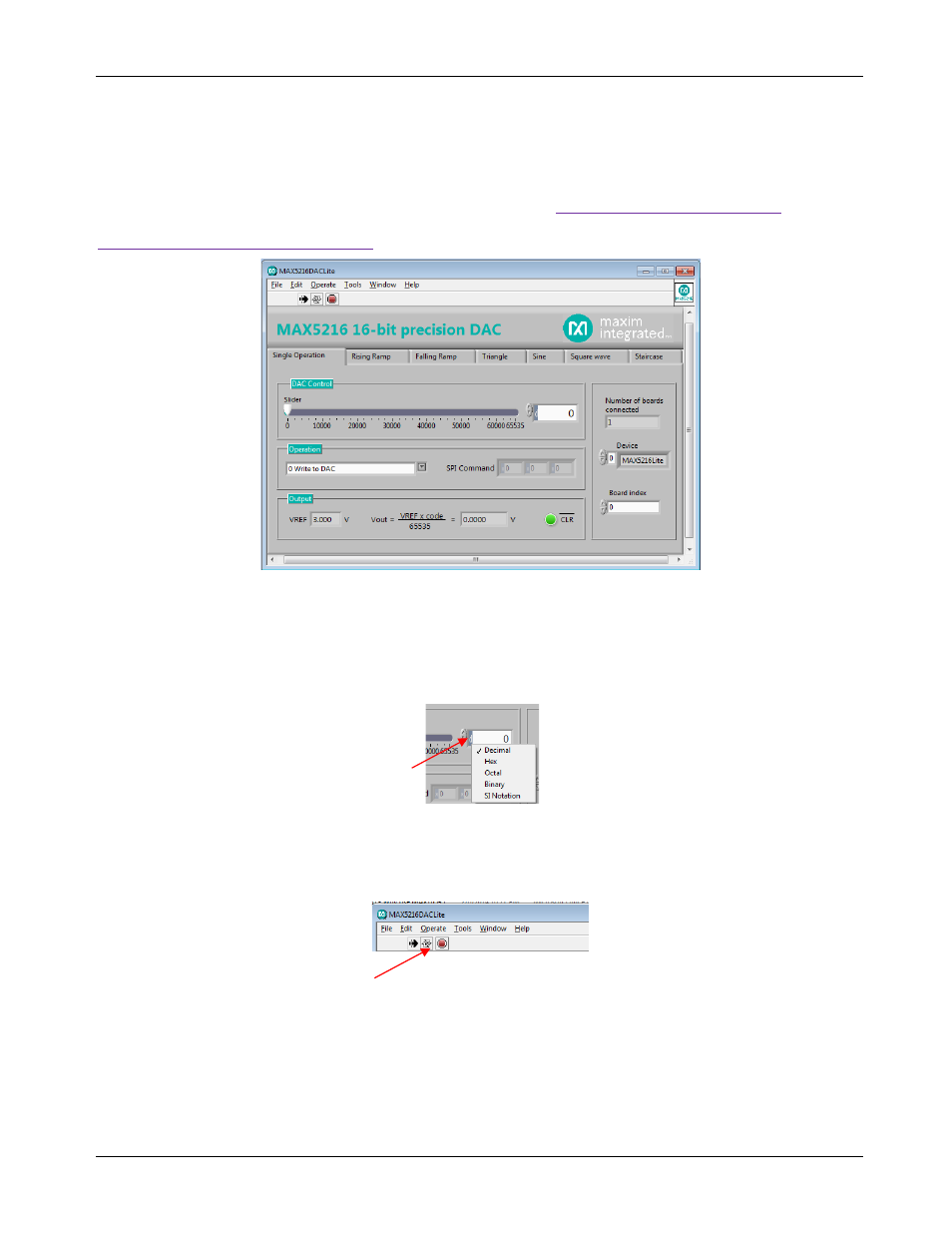
The Single Operation tab sheet is active by default. The application checks all the compatible boards
connected to the PC and indicates them on the right side of the GUI (up to 16 boards can be connected). Any
possible operation can be evaluated on the Single Operation tab sheet. For example, move the track bar slider
to set the DAC output voltage. The DAC Control spin box reflects the slider position with a decimal number.
The DAC output can also be set by typing in a decimal, hexadecimal, or an octal or binary value directly in the
DAC Control spin box. The MAX5216 accepts codes from 0 to 65535 (216-1) decimal or from 0 to FFFF hex.
The notation is displayed on the left side of the box and can be changed by clicking on the notation character.
The Rising Ramp, Falling Ramp, Triangle, Sine, Square wave, or Staircase tab sheets give the DAC the
ability to generate different waveforms with the selected parameters. There is a possible delay to start a new
waveform until the previous one finishes a full cycle when switching between tabs. To stop or start running the
signal generator application, use the toolbar at the top of the application window.
Rev 0
12