Maxim Integrated MAX11300PMB1 Peripheral Module and Munich (USB2PMB1) Adapter Board User Manual
Page 21
MAX11300PMB1 Peripheral Module and Munich (USB2PMB1) Adapter Board Quick Start Guide
Pin configurations in this example are as follows:
P0:DAC Range 0V to +10V
P1:DAC + ADC Monitoring Range 0V to +10V
P2, P5, P7, P8, P9, P11, P12, P15, P18, P19: High-Z (not used)
P3: Unidirectional Level Translator Input from P14, Output Level 5.0V
P6: GPO General Purpose Digital Output, Level 4.0V
P10: ADC (Single-Ended ADC) Range 0V to +10V
P13: ADC (Single-Ended ADC) Range 0V to +10V
P14: GPI General-Purpose Digital Input, Threshold 1.0V
P16: GPI General-Purpose Digital Input, Threshold 1.0V
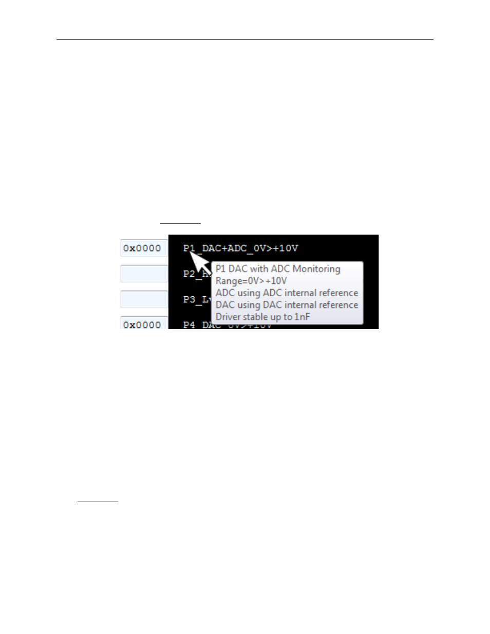
7. Hover the mouse cursor over the abbreviated pin description to obtain the detailed
description as shown in
Figure 21. Detailed Port Description
8. Select the Scan Once button under Exercise Pins. The Munich GUI then scans
through all 20 PIXI ports and executes its function. For DAC, it writes the value in the
port box to the DAC; for ADC, it reads the ADC and displays the received value into the
port box, similar to the GPIs and GPOs. Only switches and level translators are
independent, and the Munich GUI does not make any changes to them. The Scan
continuously button performs the same function as the Scan Once button, but it
repeats the scanning process until Stop Scanning is pressed.
To see results in real time, click on Scan Continuously. The Scan Continuously
button then changes to the Stop Scanning button, and the Scanning Progress bar
appears. All inputs are continuously updated (i.e., GPIs, ADCs, temperature sensors).
See
21