Keri Systems MR16out User Manual
Page 4
Mercury Security Corporation © 2009
MR16out
DOC 10107-0010
REV 2.01
Page 4
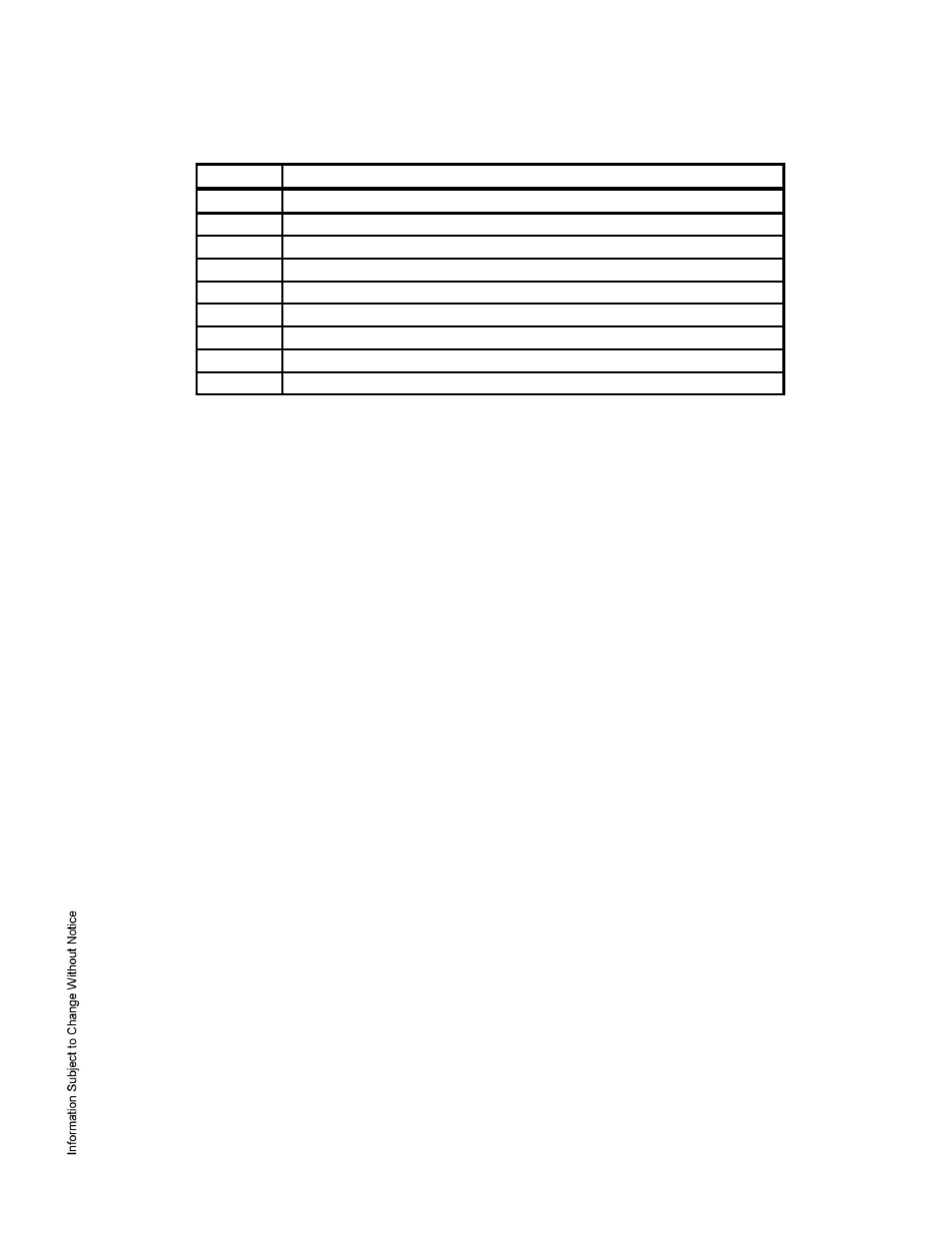
Jumpers:
JUMPER
DESCRIPTION
J1
RS-485 termination, install in first and last units only
J2
Not used
J3
2-wire/4-wire select, install in 2W position only
J4
Factory use only
J5
Factory use only
J6
Factory use only
J7
Factory use only
J8
Factory use only
J9
Factory use only
7. Status LEDs:
Power-
up: All LED’s OFF
Initialization: Once power is applied, initialization of the module begins
When initialization is completed, LEDs A, B, CT, and BA are briefly sequenced ON then OFF.
Run time: After the above sequence, the LEDs have the following meanings:
A LED: Heartbeat and On-Line Status:
Off-line: 1 sec rate, 20% ON
On-line:
Non-encrypted communication: 1 sec rate, 80% ON
Encrypted communication:
.1 sec ON, .1 sec OFF, .1 sec ON, .1 sec OFF, .1 sec ON, .1 sec OFF, .1 sec ON, .3 sec OFF
A LED Error Indication:
Waiting for application firmware to be downloaded: .1 sec ON, .1 sec OFF.
B LED: SIO Communication Port Status:
Indicates communication activity on the SIO communication port
CT: Cabinet Tamper
BA: Power Fault
LED 1 through 16: Illuminates when output relay OUT 1 (K1), OUT 2 (K2) is energized and so on.