Communication wiring, Inputs for cabinet tamper/power fault, Relay outputs – Keri Systems MR16out User Manual
Page 2
Mercury Security Corporation © 2009
MR16out
DOC 10107-0010
REV 2.01
Page 2
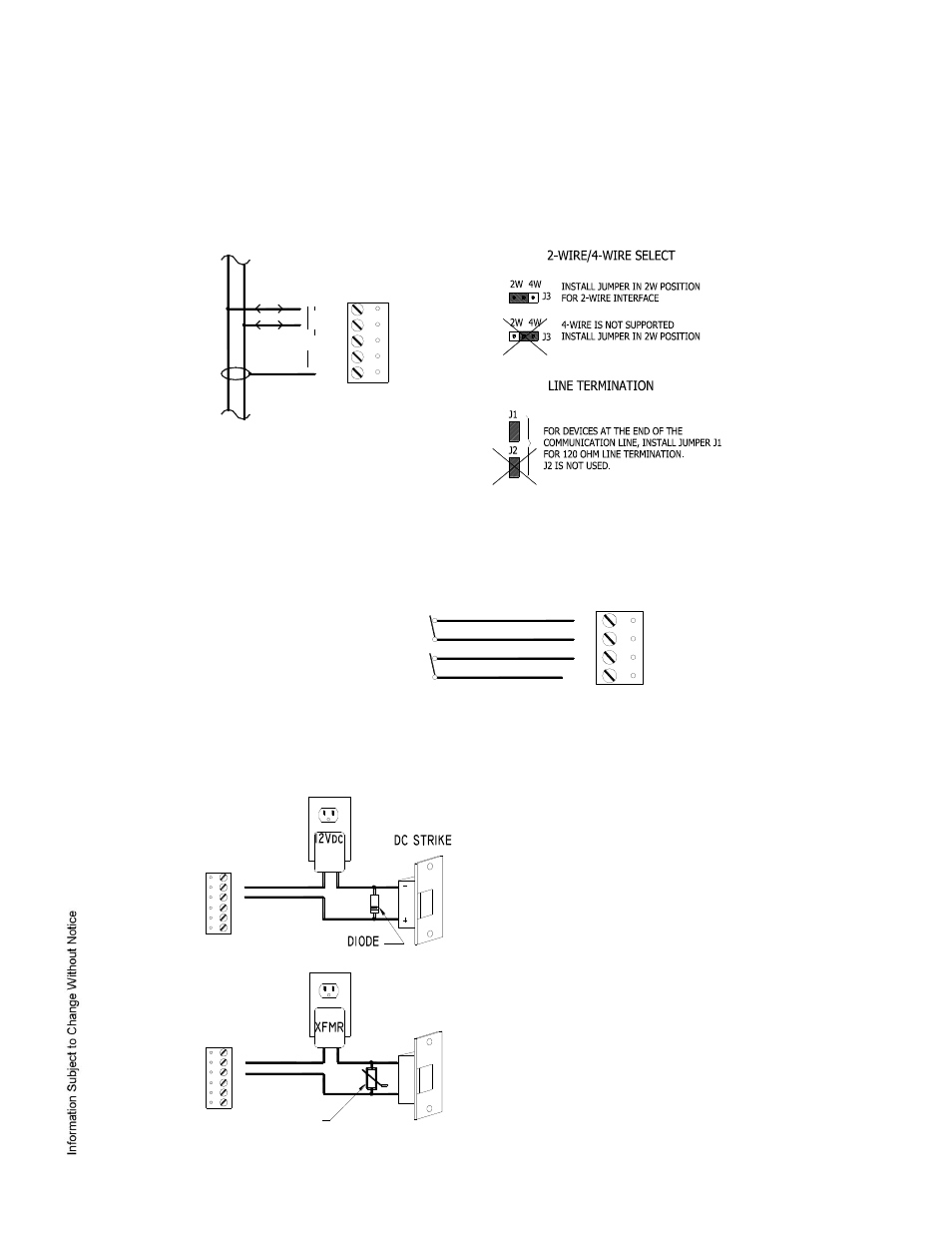
3. Communication Wiring:
The MR16out communicates to a controller via a 2-wire RS-485 interface. The interface allows multi-drop
communication on a single bus of up to 4,000 feet (1,200 m). Use twisted pair (minimum 24 AWG) with
shield for the communication line.
Install the following jumpers for the RS-485 interface according to the selected configuration:
4. Inputs for Cabinet Tamper/Power Fault:
Input CT and input BA are used for monitoring cabinet tamper and power failure with normally closed
contacts. These two inputs are for contact closure monitoring only, and do not use EOL resistor(s). If
these inputs are not used, install a short piece of wire at the input to indicate a safe condition.
5. Relay Outputs:
The following diagrams show typical use of the relay. A DC power source is recommended whenever
possible. Transient clamping must be provided to protect the contacts and to reduce EMI emission. Use
sufficiently large wires for the load current to avoid voltage loss.
DIODE SELECTION:
DIODE CURRENT RATING > 1 X STRIKE CURRENT
DIODE BREAK DOWN VOLTAGE: 4X STRIKE VOLTAGE
FOR 12Vdc or 24Vdc STRIKE, DIODE 1N4002 (100V /1A)
TYPICAL
MOV SELECTION:
CLAMP VOLTAGE > 1.5 X Vac RMS
FOR 24Vac STRIKE, PANASONIC ERZ-C07DK470
TYPICAL
CT
GND
BA
GND
CABINET
TAMPER
POWER
FAULT
TB9
NC
C
NO
NC
C
NO
NC
C
NO
NC
C
NO
TR+
TR-
R+
R-
GND
2W
4W
2-WIRE
TB10
(ONLY 2-WIRE RS-485 IS SUPPORTED)