0 resetting the controller's ram, 0 controller addressing, 1 the master controller – Keri Systems PXL-380 User Manual
Page 5: Pxl-380 access controller
PXL-380 Access Controller
Installation Guide
Page 5 of 7
P/N: 01239-002 Rev. D
9.
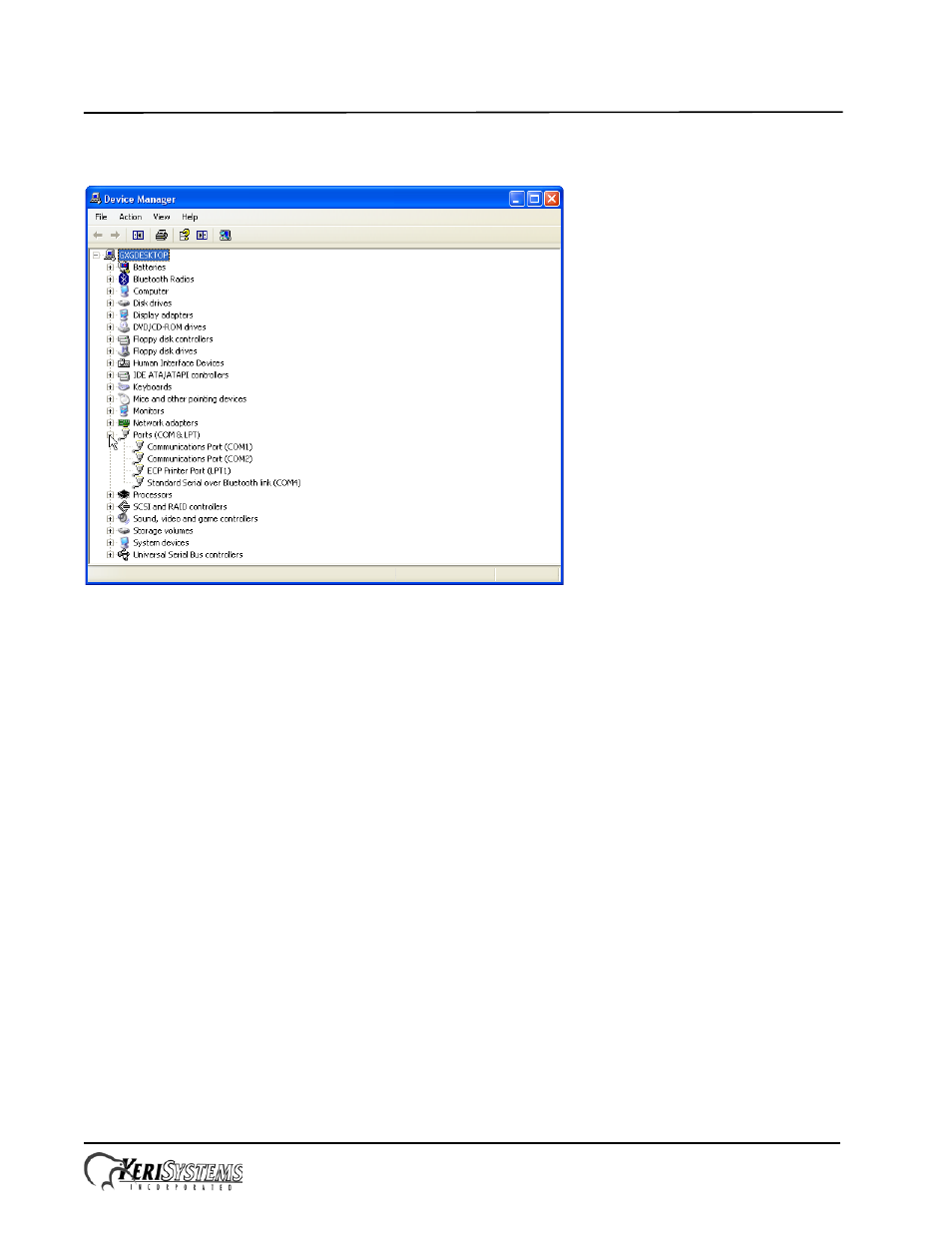
Disconnect the USB cable and note the COM port that disappears. This is the COM port assigned to the Comm
Board.
10. Reconnect the USB cable and verify the COM port reappears with the same port assignment.
11. Note this COM port number assigned to the Comm Board for assignment in Doors.NET.
4.0
Resetting the Controller's RAM
If you're turning system power on for the first time or have just changed the EPROM/PIC, the PXL-380 controller's RAM
must be reset before performing any other action. This clears any spurious information that may be in the RAM in
preparation for entering your access control information. Before applying power, insert a jumper across pins 1 and 2 of
JP10 on the controller. Hold the S1 Options Button down and turn the controller's power on. The beeper for the reader
attached to the controller will beep as power comes on followed by a beep-beep indicating the controller's firmware has
reset the controller's RAM. Release S1. Turn system power off and remove the jumper on JP10. When the controller is
powered up it is now ready to receive information from Doors.NET.
NOTE: Resetting the system RAM completely erases all information within the PXL-380 controller. Therefore, once a
reset has been performed on the controller all the access control information will need to be sent again from the software.
5.0
Controller Addressing
To view the controller's address, click S1. The controller's address will appear on the address display for 2 to 3 seconds.
5.1
The Master Controller
Every site must have one Master Controller, through which communication to the host PC is made and to which all slave
controllers are connected. The Master Controller must be set as address 1 and it must have the Master Controller jumper
JP 11 ON (refer to the drawing on page 1). All slave controllers must not have a jumper on JP11 and can have addresses
between 2 and 128. A Comm Board is required for the Master Controller to communicate with the host PC. The Comm
Board is not provided with PXL controllers, but must be ordered separately. Refer back to Section 3.0 for information on
the Comm Board.