Pin configuration, Product portfolio – Cypress CY62158E User Manual
Page 2
CY62158E MoBL
®
Document #: 38-05684 Rev. *D
Page 2 of 10
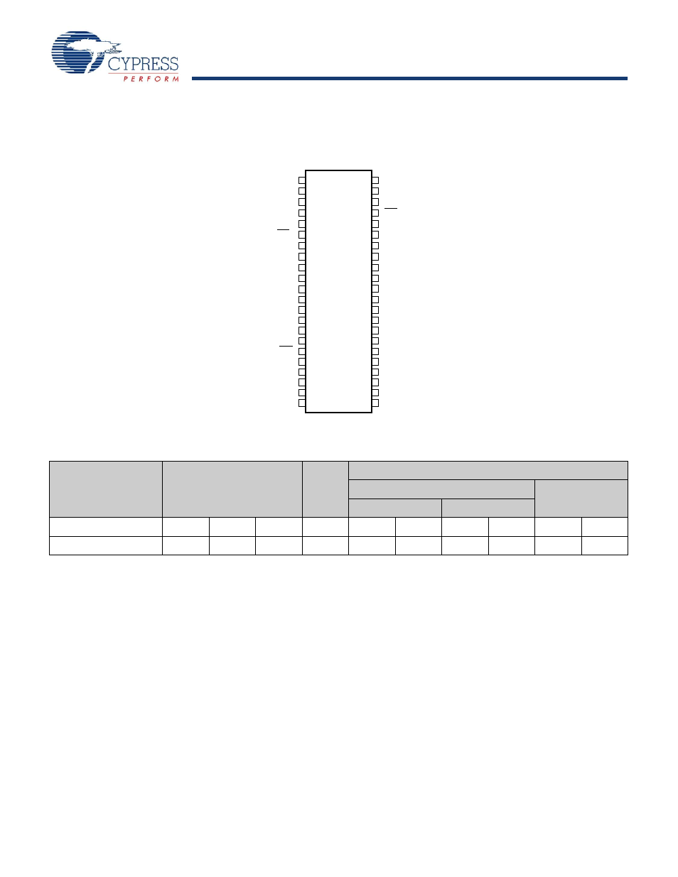
Pin Configuration
Figure 1. 44-Pin TSOP II (Top View)
Product Portfolio
Product
V
CC
Range (V)
Speed
(ns)
Power Dissipation
Operating I
CC
(mA)
Standby I
SB2
(
μA)
f = 1 MHz
f = f
max
Min
Typ
Max
Typ
[2]
Max
Typ
[2]
Max
Typ
[2]
Max
CY62158ELL
4.5
5.0
5.5
45
1.8
3
18
25
2
8
1
2
3
4
5
6
7
8
9
11
14
31
32
36
35
34
33
37
40
39
38
12
13
41
44
43
42
16
15
29
30
A
5
18
17
20
19
23
28
25
24
22
21
27
26
A
6
A
7
A
4
A
3
A
2
A
1
A
0
A
17
A
18
A
10
A
11
A
12
A
13
A
15
A
16
A
14
OE
CE
2
A
8
CE
1
WE
NC
NC
IO
0
IO
1
IO
2
IO
3
NC
NC
NC
NC
IO
4
IO
5
IO
6
IO
7
NC
NC
V
CC
V
CC
V
SS
V
SS
A
9
10
A
19
Notes
1. NC pins are not connected on the die.
2. Typical values are included for reference only and are not guaranteed or tested. Typical values are measured at V
CC
= V
CC(typ)
, T
A
= 25°C.
See also other documents in the category Cypress Hardware:
- CY7C1410AV18 (29 pages)
- CY7C1411JV18 (28 pages)
- CY7C1383FV25 (28 pages)
- CY14B256L (18 pages)
- CY7C1307BV25 (21 pages)
- CY7C1041DV33 (13 pages)
- CY62167EV18 (13 pages)
- Perform CY7C1565V18 (28 pages)
- STK11C68-5 (15 pages)
- 7C185-20 (11 pages)
- CY7C1168V18 (27 pages)
- CY7C1318CV18-250BZC (26 pages)
- CY7C1364C (18 pages)
- Perform CY7C1382D (34 pages)
- CY7C106D (11 pages)
- CY14E102N (21 pages)
- CY7C1418AV18 (31 pages)
- enCoRe CY7C638xx (83 pages)
- CY7C1018DV33 (9 pages)
- CY7C1292DV18 (23 pages)
- CY7C130 (19 pages)
- CY7C1424BV18 (30 pages)
- CY62157EV18 (12 pages)
- CY7C1392BV18 (31 pages)
- CY7C1302DV25 (18 pages)
- Perform CY7C1511KV18 (31 pages)
- West Bridge Astoria AN46860 (4 pages)
- CY7C1386FV25 (30 pages)
- CY7C1163V18 (29 pages)
- CY7C1266V18 (27 pages)
- CY7C1334H (13 pages)
- CY7C1018CV33 (7 pages)
- CY62136VN (12 pages)
- AN20639 (3 pages)
- CY7C1338G (17 pages)
- CY7C1462AV33 (27 pages)
- CY7C1145V18 (28 pages)
- STK11C88 (15 pages)
- CY7C1231H (12 pages)
- Perform CY7C142 (15 pages)
- CY14E256L (18 pages)
- STK15C88 (15 pages)
- CY7C1297H (15 pages)
- CY7C1441AV33 (31 pages)
- CapSense CY8C20x36 (34 pages)