Electrical, Dvhvac36, General venting – Vermont Casting DVHVAC36 User Manual
Page 9: Fig. 8 dvhvac36 wiring diagram
9
DVHVAC36
10001195
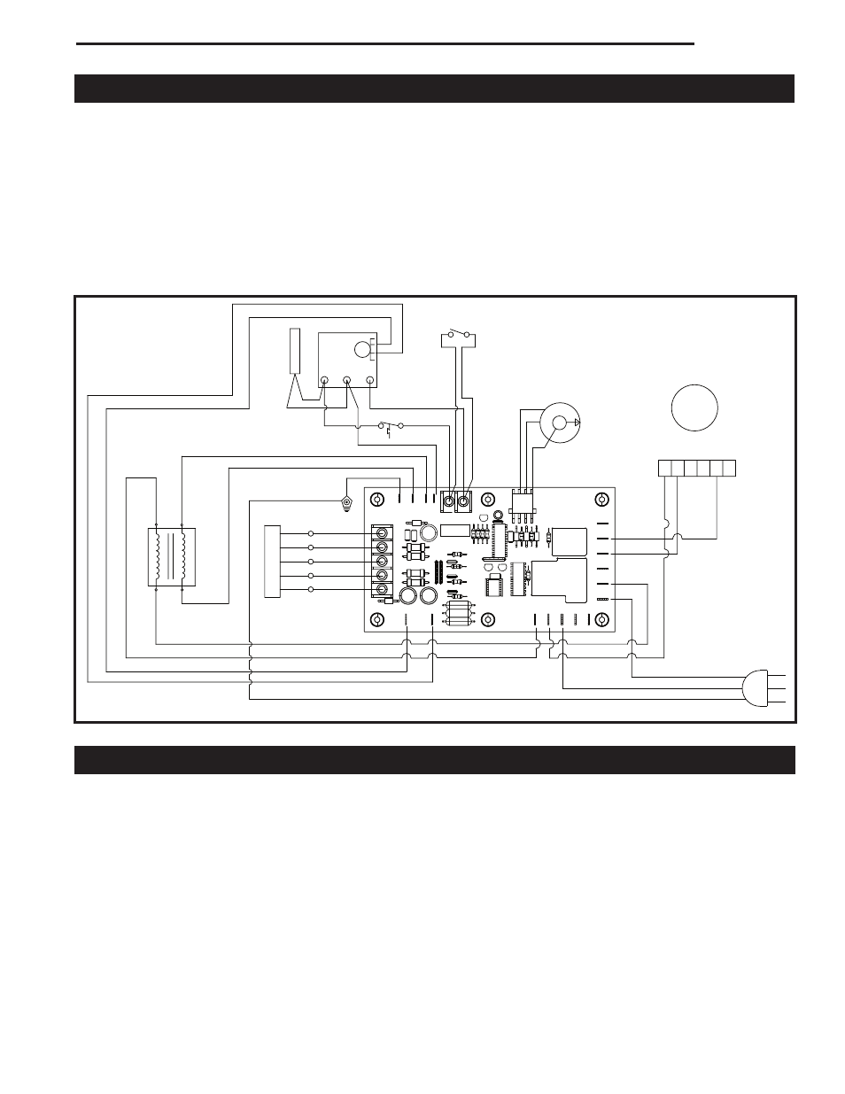
Electrical
Refer to Figure 8 for field wiring.
1. Select fuse and wire size according to rating plate
amperage.
2. Install a separate fused disconnect switch near the
unit for service purposes.
3. Knockouts are provided on both sides of cabinet for
electrical wiring.
4. Install room thermostat (24 volt) according to
instructions provided with thermostat, using 18
gauge wire or larger.
5. Electrically ground the unit in accordance with
local codes, or in the absence of local codes in
accordance with the Canadian Electrical Code, Part
1 (CSA Standard C22.1) in Canada, or with the
National Electric Code (ANSI/NFPA No. 70) in the
United States.
6. The circuit board is equipped with two (2) accessory
terminals. The terminal marked "Air Cleaner" and
"Humidifier" are rated for 120V 0.5 Amps and are
energized with the air circulating blower. Connect the
neutral leg of the accessory to the 120V neutral wire.
Fig. 8 DVHVAC36 wiring diagram.
FP1413
1
2
3
4
5
6
COMMON
NOT USED
MED-HI
MED-LO
LOW
NOT USED
ACB
FLAME
ADJUST
ORANGE/BLACK
BROWN
ORANGE
HUMIDIFIER
ACB HEAT
ACB COOL
AIR CLEANER
XFORMER 1
2 RED
3 BLACK
1 WHITE
110 VAC HOT
110 VAC RTN
110 VAC HOT
CLEAN RTN
HUMID RTN
10 VAC RTN
ACB RTN
X FORMER
2
SOLENOID
2
SOLENOID
1
9 YELLOW
6 BLACK
7 WHITE
8 BLUE
8 BLUE
3
5
1
4
THERMOSTAT
11 GREEN
10 BLUE
R
W1
G
Y
GND
CHASSIS GND
24 VAC RTN
24 VAC HOT
TH TP-PILE
+
TH-PILE
+
THERMOPILE
GAS VALVE
TP/TH
TP
TH
EMERGENCY
HEAT
SWITCH
14 YELLOW
15 BLUE
13 BLUE
12 YELLOW
RED
WHITE
L1
L2
TP/TH
TH
LIMIT
16 YELLOW
17 GREEN
TP
4 RED
5 WHITE
18 GRAY
19 YELLOW
20 GREEN
GREEN
FP1413
DVHVAC36
wiring diagram
11/03
This model is approved to be vented either through the
side wall, or vertically through the roof.
•
Only venting components specifically approved and
labelled for this fireplace may be used.
•
Minimum clearances between vent pipes and com-
bustible materials is 1" (25 mm).
•
Venting terminals shall not be recessed into a wall or
siding.
•
Horizontal venting must be installed on a level plane
without an inclining or declining slope.
There must not be any obstruction such as bushes,
garden sheds, fences, decks or utility buildings within
General Venting
24" (610 mm) from the front of the termination hood.
Do not locate termination hood where excessive snow
or ice build up may occur. Be sure to check vent termi-
nation area after snow falls, and clear to prevent ac-
cidental blockage of venting system. When using snow
blowers, make sure snow is not directed towards vent
termination area.
Location of Vent Termination
It is imperative that the vent termination be located ob-
serving the minimum clearances as shown on Page 10.
*Check with local codes or in absence of same with
CSA B149.1 Installation Codes (1991) for Canada or for
U.S.A. Installations follow the current National Fuel Gas
Code, ANSI Z223.1/NFPA 54.