Vermont Casting DVHVAC36 User Manual
Page 21
21
DVHVAC36
10001195
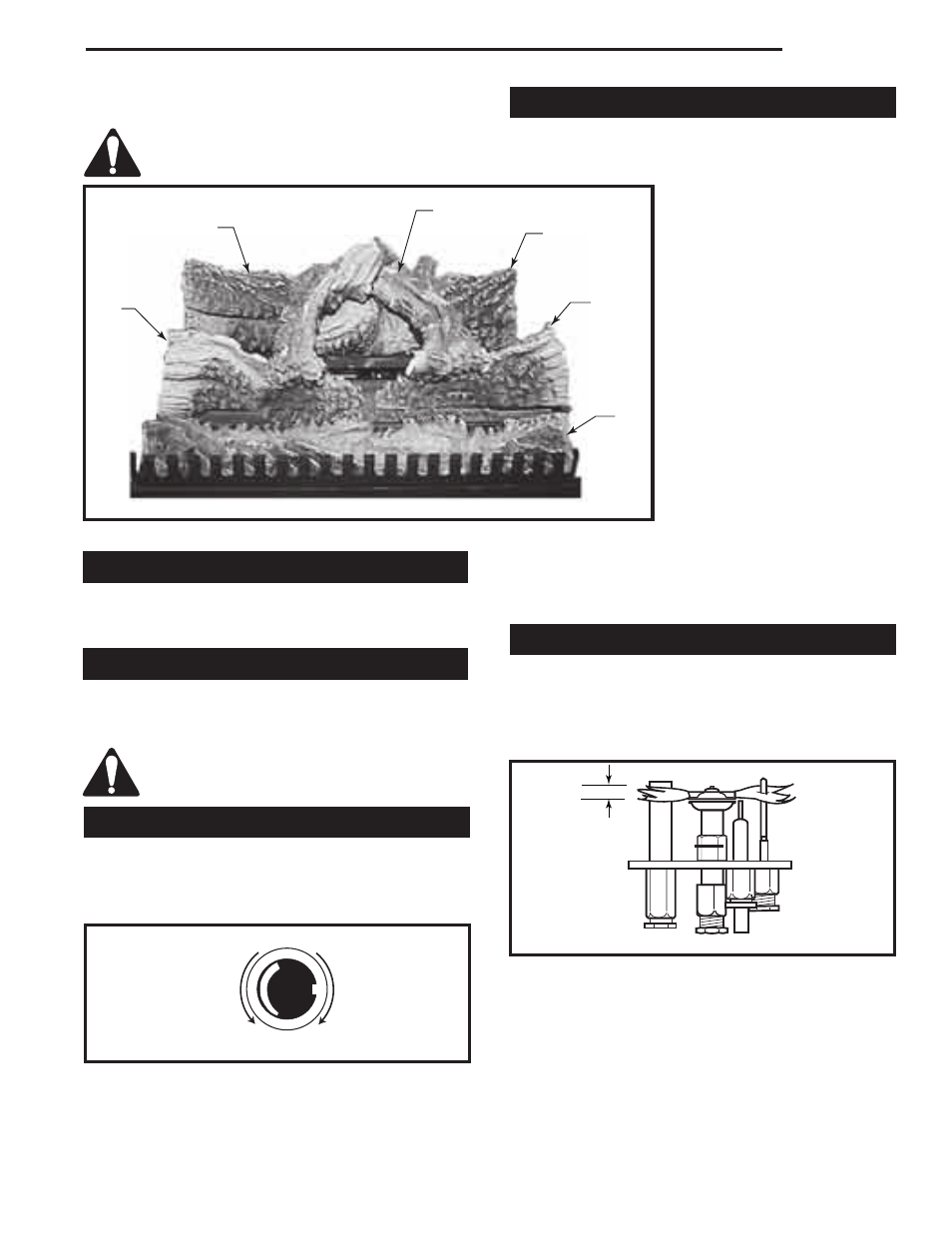
9. Place top left log (B16) onto locator notches. Ensure
log is secure.
Top logs must be placed properly onto
notches.
LG310
DVHVAC
logs
8/03
B13
B16
B17
B15
B14
B12
LG310
Fig. 37 DVHVAC36 log placement.
Setting Temperature Rise
With the unit installed and operating at equilibrium,
adjust the temperature rise through the unit to between
25° and 50° Farenheit.
Lava Rock
The lava rock provided with this fireplace must be
placed on the firebox base on either side of the burner
assembly.
Under no circumstances should this lava
rock be placed on any part of the burner
assembly.
Flame Adjustment
The DVHVAC36 is equipped with a HI/LO flame adjust-
ment knob located on the front of the electrical junction
box. Rotating the knob will adjust the flame height and
heat output of the unit. (Fig. 38)
Emergency Heat
In the event of a power outage, the DVHVAC36 unit can
be run in an emergency heat mode. Simply turn the unit
on by toggling the rocker switch located on the front of
the electrical junction box to the
"ON" position. This will turn on
the fireplace burner in a low fire
condition. The unit will provide
heat to the room in which the
fireplace is installed. When power
is restored, toggle the emergency
heat switch to the "OFF" position.
NOTE: When in the emergency
heat mode, the air circulating fan
will not operate. In order to pre-
vent overheating of the duct work,
the unit will periodically cycle on
and off. The length of cycles will
depend upon factors such as the
length and design of the duct-
work, interior temperature and
venting arrangements.
NOTE: When the electricity is off,
the thermostat will not operate
the unit. The unit must be controlled manually through
the emergency heat switch located on the front of the
electrical junction box.
Flame Characteristics
It is important to periodically perform a visual check
of the pilot and the burner flames. Compare them to
Figures 39 & 40. If any of the flames appear abnormal,
contact a qualified service provider for service and
adjustment.
Fig. 38 Flame adjustment knob for SIT valve.
LO
HI
FP390
FLAME ADJUSTMENT KNOB
11/21/96
Turn
counterclockwise
to increase
flame height
Turn clockwise
to decrease
flame height
3/8" - 1/2"
FP1229a
Pilot flames
11/02
FP1229a
Fig. 40 Correct pilot flame appearance.