Dvhvac36, Vertical sidewall installations – Vermont Casting DVHVAC36 User Manual
Page 15
15
DVHVAC36
10001195
•
IMPORTANT
•
Minimum clearance between vent
pipes and combustible materials is 1" (25mm) on bot-
tom, sides and top.
A vent starter kit plus a transition elbow
must be used in Vertical Sidewall Installa-
tions. The 4" pipe must be centered inside
the 7" pipe coming off the transition elbow.
Canadian & USA Installations:
The venting system must conform with local codes, or
in the absence of local codes, with the National Fuel
Gas Code, ANSI Z223.1/NFPA 54 - latest edition, or
CSA B149.1 Installation Code.
Only CFM Corporation venting components specifically
approved and labelled for this fireplace may be used.
Vertical Sidewall Installations
STEP 1
Locate vent opening on the wall. It may be necessary
to first position the fireplace and measure to obtain hole
location. Depending on whether the wall is combustible
or noncombustible, cut opening to size. (Fig. 22)
For combustible walls first frame in opening.
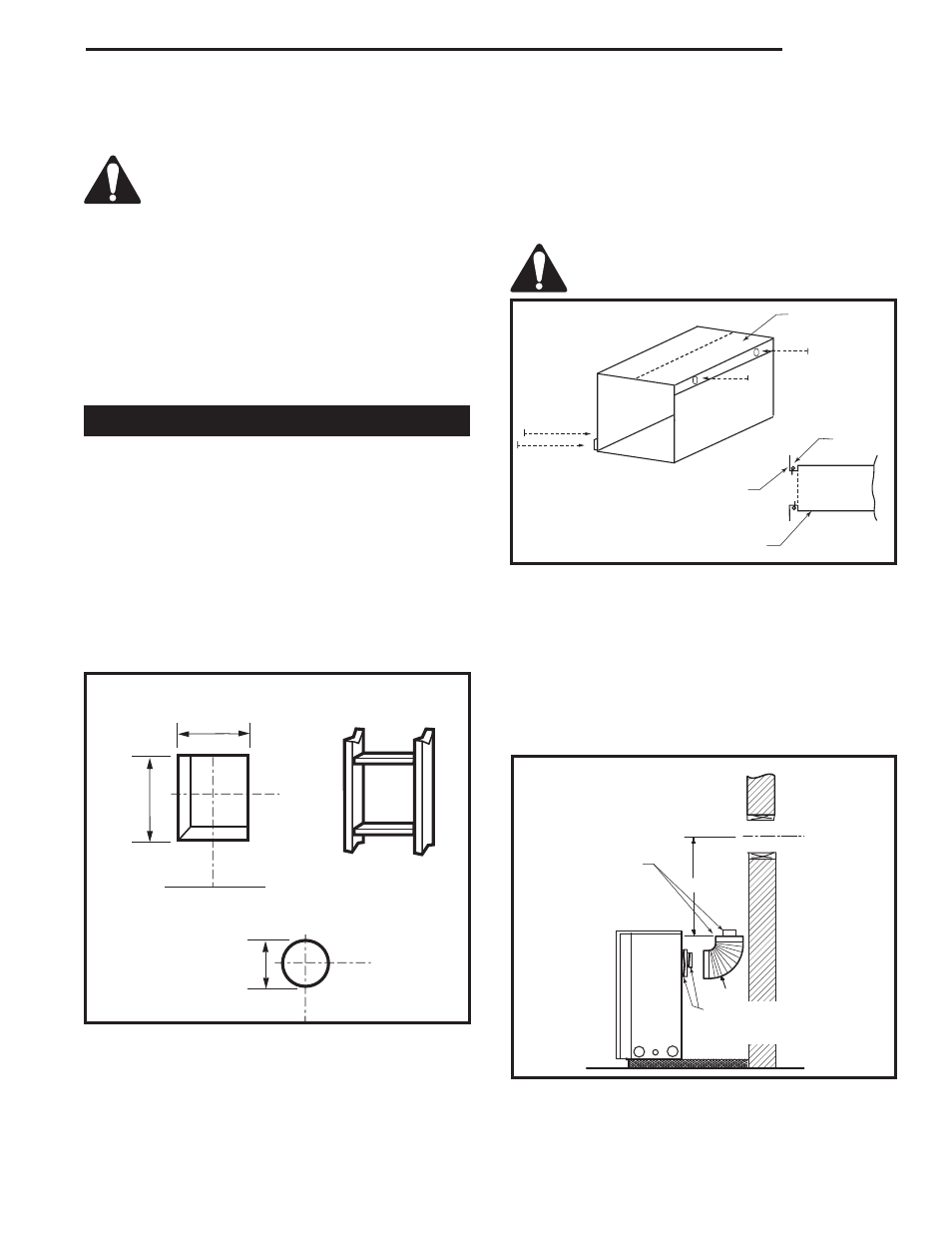
Combustible Walls (Fig. 22): Cut a 9³⁄₈" x 9³⁄₈" (240 x
240 mm) hole through the exterior wall and frame.
Noncombustible Walls (Fig. 22): Hole opening must
be 7¹⁄₂" (190 mm) in diameter.
VO584-100
Vent Opening
2/99 djt
Vent Opening for Combustible Wall
9³⁄₈"
(240 mm)
9³⁄₈"
(240 mm)
Fireplace
Hearth
Framing
Detail
Vent Opening for Noncombustible Wall
7¹⁄₂"
(190 mm)
VO584-100
Fig. 22 Locate vent opening on wall.
STEP 2
Measure wall thickness and cut adjustable zero clear-
ance sleeve parts to proper length (MAXIMUM 12" /
305mm). (Fig. 23) Adjust sleeve to minimum (9³⁄₈" x 9³⁄₈"
/ 240 x 240 mm) and attach to firestop with #8 sheet
metal screws (supplied). Assemble sleeve and attach
to firestop with #8 sheet metal screws (supplied). Install
firestop assembly.
Zero clearance sleeve is only required for
combustible walls.
ZCS101
Zero Clearance Sleeve
3/11/99 djt
Max. Length
12" (305 mm)
Adjustable
Zero Clearance
Sleeve
#8 Screws
(2)
#8 Screws (2)
#8
Screws
(2)
Firestop
Adjustable Zero Clearance Sleeve
ZCS101
Fig. 23 Adjustable zero clearance sleeve.
STEP 3
Apply a bead of high temperature sealant to the inner
and outer flue collars of the fireplace and using ap-
propriate venting component(s) attach to fireplace with
three (3) screws. (Fig. 24) Follow with the installation
of the inner and outer elbow. Again, secure joints with
three (3) sheet metal screws. Wipe off any excess high
temperature sealant.
�
��������
CFM143
2/2/01 sta
CFM143
Ensure Pipes
are Concentric
Bead of Seal-
ant
(If Necessary)
Fig. 24 Apply sealant to inner and outer pipe.