Dvhvac36, Vertical sidewall applications – Vermont Casting DVHVAC36 User Manual
Page 13
13
DVHVAC36
10001195
VO584-100
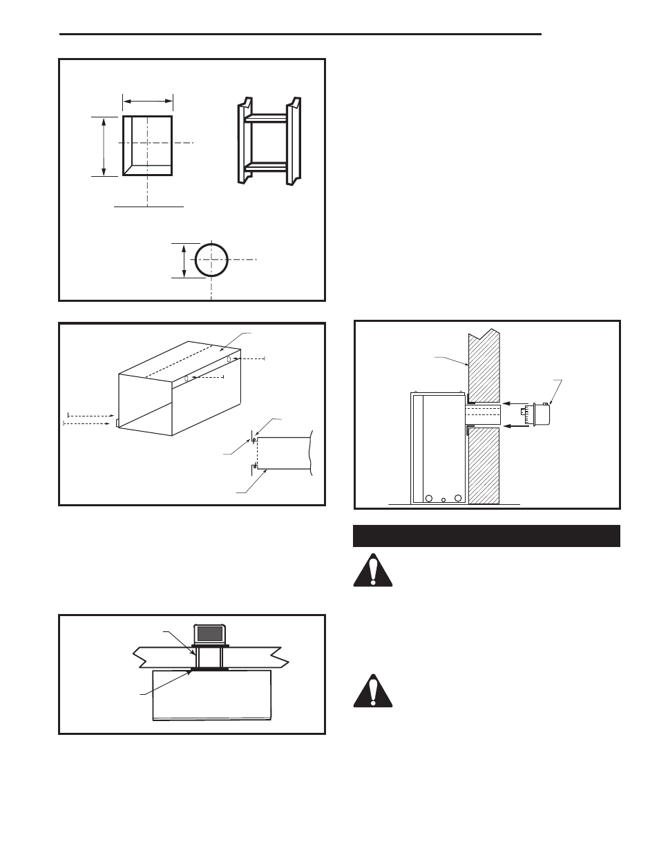
Vent Opening
2/99 djt
Vent Opening for Combustible Wall
9³⁄₈"
(240 mm)
10³⁄₈"
(265 mm)
Fireplace
Hearth
Framing
Detail
Vent Opening for Noncombustible Wall
7¹⁄₂"
(190 mm)
VO584-100
Fig. 14 Locate vent opening on wall.
ZCS101
Zero Clearance Sleeve
3/11/99 djt
Max. Length
12" (305 mm)
Adjustable
Zero Clearance
Sleeve
#8 Screws
(2)
#8 Screws (2)
#8
Screws
(2)
Firestop
Adjustable Zero Clearance Sleeve
ZCS101
Fig. 15 Adjustable zero clearance sleeve.
STEP 3
Measure from fireplace collar face to face of outside
wall (add 2" (51 mm) for vent pipe overlap). Mark pipes
and cut to length. It is very important that the two pipes
are flush with the outside wall once the fireplace is in its
final location. (Fig. 16)
FP1404
DVHVAC
vent pipe
8/03
Zero Clearance Sleeve
Firestop
FP1404
Fig. 16 Firestop and zero clearance sleeve in place.
STEP 4
Slip 4" (102 mm) and 7" (178 mm) pipes onto respec-
tive flue collars. Make sure to fix to the fireplace collar
the 4" pipe with three (3) screws before fixing the 7"
pipe on the 7" collar. Both pipes must be on a level
plane. (Fig. 17)
STEP 5
Guide the vent termination 4" collar into the 4" pipe then
the 7" collar into the 7" pipe. Do not force the venting
into position. If the pipes do not line up with the termina-
tion collars, disassemble elbows or pipes and reattach
to the fireplace collar.
STEP 6
Recheck the fireplace to make sure it is levelled, prop-
erly positioned and nailed or screwed to the floor.
If applied, the fireplace adjustable frame drywall strips
(nailing flanges) should be fastened. Refer to Framing
and Finishing.
Vertical Sidewall Applications
Since it is very important that the vent-
ing system maintain its balance between
the combustion air intake and the flue
gas exhaust, certain limitations as to vent
configurations apply and must be strictly
adhered to.
The graph showing the relationship between vertical
and horizontal side wall venting will help to determine
the various vent lengths allowable. (Fig. 12)
Minimum clearance between vent pipes
and combustible materials is 1" (25 mm)
on top, bottom and sides unless otherwise
noted.
When vent termination exits through foundation less
than 20" (508 mm) below siding outcrop, the vent pipe
must flush up with the siding. A 7DVSS must also be
used.
FP1005
Side View Vent Termination
1/25/00 djt
Finished
Wall
Vent Termi-
nation
FP1005
Fig. 17 Side view of final unit location.