Dvhvac36, How to use the vent graph, Corner installation – Vermont Casting DVHVAC36 User Manual
Page 12: Rear wall venting applications, Rear wall installations, Sidewall venting graph
12
DVHVAC36
10001195
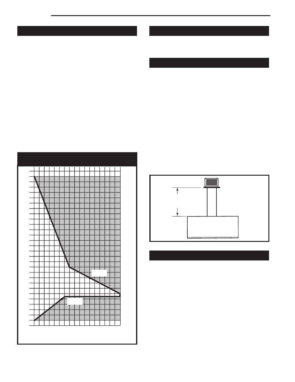
How to Use the Vent Graph
1. Determine the height of the center of the horizontal
vent pipe exiting through the outer wall. Using this
dimension on the Sidewall Vent Graph (Fig. 12),
locate the point it intersects with the slanted graph
line.
2. From the point of this intersection, draw a vertical
line to the bottom of the graph.
3. Select the indicated dimension, and position the fire-
place in accordance with same. (Refer to examples
Fig. 12)
EXAMPLE A:
If the vertical dimension from the floor of the unit is 11'
(3.4m) the horizontal run to the face of the outer wall
must not exceed 14' (4.3 m).
EXAMPLE B:
If the vertical dimension from the floor of the unit is 7'
(2m), the horizontal run to the face of the outer wall
must not exceed 8¹⁄₂' (2.6 m).
Corner Installation
When the DVHVAC36 unit is installed in a corner,
Figure 1, Option B, the vent configuration must fol-
low the Vertical Sidewall Installation Instructions.
Rear Wall Venting Applications
This appliance may be vented directly to a termination
located on the rear wall behind the appliance.
NOTE: It is not necessary to seal the vent pipe joints for
any rear vent applications.
•
Only CFM Corporation venting components are
approved to be used in these applications. Refer to
“Venting Components” listed for different installation
requirements.
•
The maximum horizontal distance between the rear
of the appliance and the outside face of the rear wall
is 20” (508 mm). (Fig. 13)
•
Minimum clearances between vent pipe and com-
bustible materials are as follows:
Top - 2” (51 mm)
Sides - 1” (25 mm)
Bottom - 1” (25 mm)
Rear Wall Installations
STEP 1
Locate vent opening on wall. To locate hole center, refer
to appropriate fireplace dimensions on Page 4.
Combustible Walls (Fig. 14): Cut a 10³⁄₈" x 9³⁄₈" (265 x
240 mm) hole through the exterior wall and frame as
shown.
Noncombustible Walls (Fig. 14): Hole opening must be
7¹⁄₂" (191 mm) in diameter.
STEP 2
Measure wall thickness and cut adjustable zero clear-
ance sleeve parts to proper length (MAXIMUM 12" /
305 mm). Adjust sleeve to maximum (10³⁄₈" x 9³⁄₈" / 265
x 240 mm) and attach to firestop with #8 sheet metal
screws (supplied). (Fig. 15) Install firestop assembly.
20"
(508mm)
FP1403
DVHVAC
rear vent app
8/03
FP1403
Fig. 13 Rear vent application.
V
ertical dimension from the fl
oor of the unit
to the center of the horizontal vent pipe
3
4
5
6
7
8
9
10
11
12
13
14
15
16
17
18
19
20
21
22
23
24
25
26
27
28
29
30
3 4 5 6 7 8 9 10 11 12 13 14 15 16 17 18 19 20
eg: A
eg: B
CFM102
DV Graphic
9/28/00 sta
Sidewall Venting Graph
(Dimensions in Feet)
Horizontal dimension from the outside face of the wall
to the center of the fireplace vent flange
Fig. 12 Sidewall venting graph. (Dimensions in feet)