Vermont Casting DVHVAC36 User Manual
Page 22
22
DVHVAC36
10001195
Inspecting the Venting System
This appliance venting system was designed and con-
structed to develop a positive flow adequate to remove
flue gases to the outside atmosphere.
Any foreign objects in the venting system, except those
designed specifically for the venting system, may cause
spillage of flue gases.
To inspect the venting heat exchanger system, make
sure the main gas valve is off. Remove window frame
assembly. (Refer to Window Frame Assembly Removal
section) Using a flashlight, check the area above the
baffle in the combustion dome. Clean if necessary.
Inspecting the Venting/Heating
Exchange System
Any foreign objects or corrosion in the heat exchanger
or venting system may cause spillage or leakage of the
gases into the living space.
Ceramic Refractory Installation
1. Remove window frame assembly and logs.
2. Place refractory side supports so that the hole fits
over the screw head on the firebox floor.
3. Place refractory base sides on the floor of the fire-
box.
4. Attach adjustable tabs, packed with refractory, onto
the studs found on the top of the firebox using the
2-10/24 nuts provided.
5. Place back refractory - small brick edge down into
support and swing into position. (Fig. 41)
6. Slide side panels into side supports and behind side
tab and adjust, fitting the ceramic tight to the side of
the firebox. Tighten nuts. (Fig. 42)
Mortar lines must be aligned.
FP1231
Ceramic panels
11/02
Adjustable
Tabs
Side
Panel
Base
Side Re-
fractory
Base Side Supports
Adjustable
Tabs
Side
Panel
Base Side
Refractory
Back
Panel
Log Support
Burner Tray
FP1231
Fig. 42 Ceramic refractory installation.
H102a
DVHVAC
rear ceramic support
8/21/03 djt
H102a
Rear Log Support
Refractory
Back Panel
Firebox
Back
Fig. 41 Place back refractory into support and swing into
position.
LG311
DVHVAC
log flames
8/03
LG311
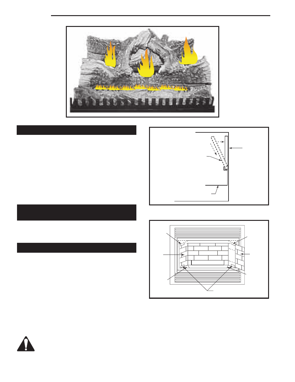
Fig. 39 Correct burner flame pattern for DVHVAC36.