Dvhvac36, Vertical through-the-roof applications, Vertical through-the-roof installation – Vermont Casting DVHVAC36 User Manual
Page 17
17
DVHVAC36
10001195
1. Establish vent hole through the wall. (Fig. 22)
2. Remove soil to a depth of approximately 16" (406 mm)
below base of snorkel. Install window well (not sup-
plied). Refill hole with 12" (305 mm) of coarse gravel
leaving a clearance of approximately 4" (102 mm)
below snorkel. (Fig. 28)
3. Install vent system. Refer to Page 12, Steps 2
through 5.
4. Ensure a watertight seal is made around the vent
pipe coming through the wall.
5. Apply high temperature sealant caulking (supplied)
around the 4" and 7" snorkel collars.
6. Slide into the vent pipe and secure to the wall.
7. Level the soil to maintain a 4" (102 mm) clearance
below snorkel. (Fig. 28)
Do not backfill around snorkel. A clearance
of at least 4" (102 mm) must be maintained
below the snorkel.
BG401
Snorkel
2/10/99 djt
Snorkel
Wall Screws
Sheet Metal
Screws
BG401
Foudation Recess
Recess Bracket
Watertight Seal
Around Pipe
Fig. 29 Snorkel installation, recessed foundation.
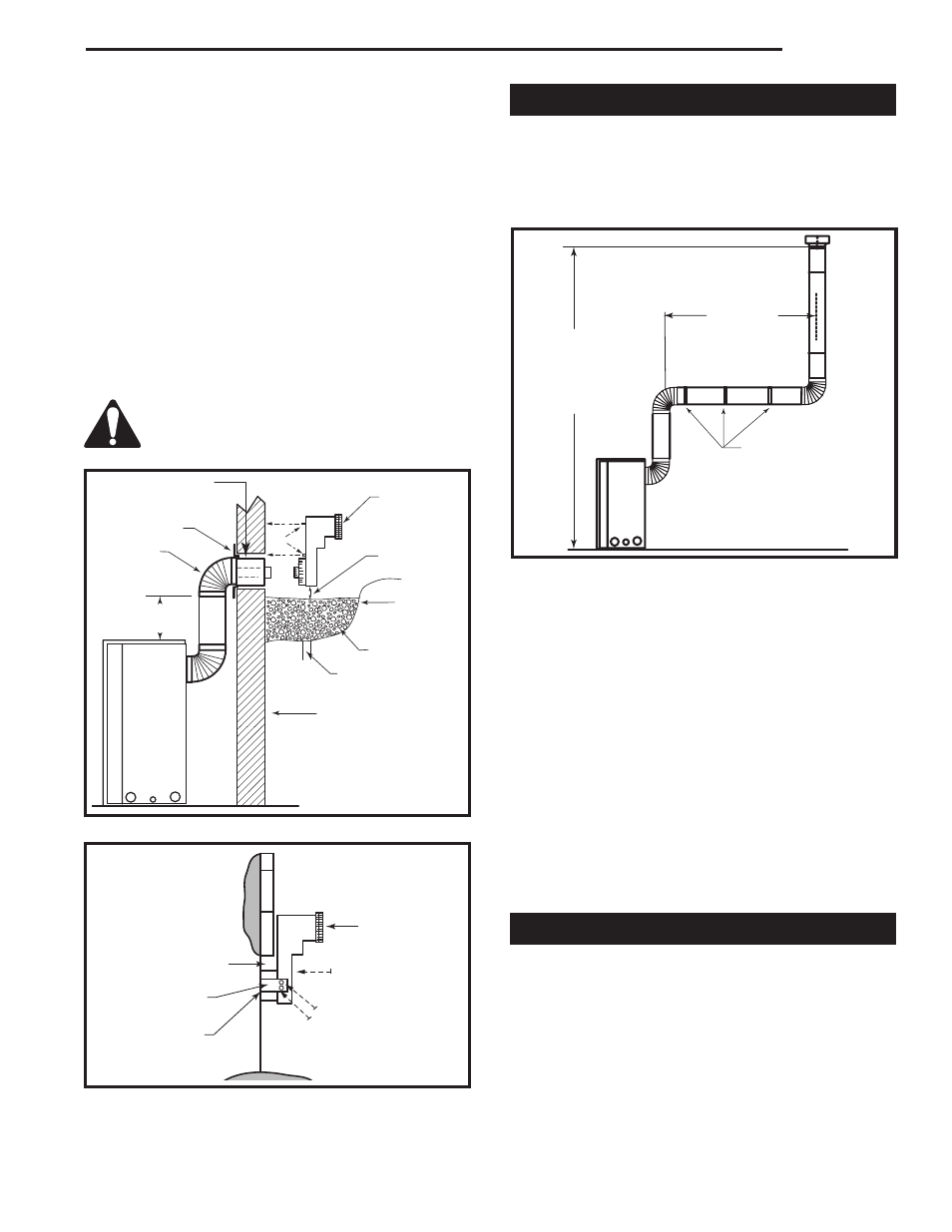
Vertical Through-the-Roof Applications
This gas fireplace has been approved for:
•
Vertical installations up to 40' (12 m) in height. Up to
10' (3 m) horizontal vent run can be installed within
the vent system using a maximum of three (3) 90°
elbows.
CFM148
Minimum 8'
(2.4m)/ Maxi-
mum 40' (12m)
Vertical Rise
Maximum
10' (3m)
Pipe Straps Every 3'
(914mm)
CFM148
Fig. 30 Support straps for horizontal runs.
•
Up to two (2) 45° elbows may be used within the
horizontal run. For each 45° elbow used on the hori-
zontal level, the maximum horizontal length must be
reduced by 18" (457 mm).
Example: Maximum horizontal length:
0 x 45° elbows = 10' (3 m)
1 x 45° elbows = 8¹⁄₂' (2.6 m)
2 x 45° elbows = 7' (2.1 m)
•
A minimum of an 8' (2.4 m) vertical rise.
•
Two (2) sets of 45° elbows offset within these verti-
cal installations. From 0 to a maximum of 8' (2.4m)
of vent pipe can be used between elbows. (Fig. 30)
•
7DVCS must be used to support offsets. (Fig. 31)
This application will require that you first determine
the roof pitch and use the appropriate 7DVSKV (A, B
or F). Refer to Venting Components on Page 21.
Vertical Through-the-Roof Installation
1. Locate your fireplace.
2. Plumb to center of the 4" flue collar from ceiling
above and mark position.
3. Cut opening equal to 9³⁄₈" x 9³⁄₈" (240 x 240 mm).
4. Proceed to plumb for additional openings through
the roof. In all cases, the opening must provide a
minimum of 1" clearance to the vent pipe, i.e., the
hole must be at least 9³⁄₈" x 9³⁄₈" (240 x 240 mm).
BG400
Below grade installation
2/10/99 djt
10/19/99 added standoffs
24" (608mm)
Minimum*
Zero Clearance
Sleeve
Firestop
7" Pipe
7TDVSNORK
(Snorkel)
4" (102mm)
Clearance
Min.
Window
Well
Gravel
Drain
Foundation Wall
Screws
BG400
Fig. 28 Below grade installation.
*A minimum of 24" (608mm)
vertical pipe must be installed
when using the 7TDVSNORK
Kit.