Figure 1-18 – Cisco 7200 VXR User Manual
Page 36
1-36
Cisco 7200 VXR Installation and Configuration Guide
OL-5013-09
Chapter 1 Cisco 7200 VXR Product Overview
Field-Replaceable Units
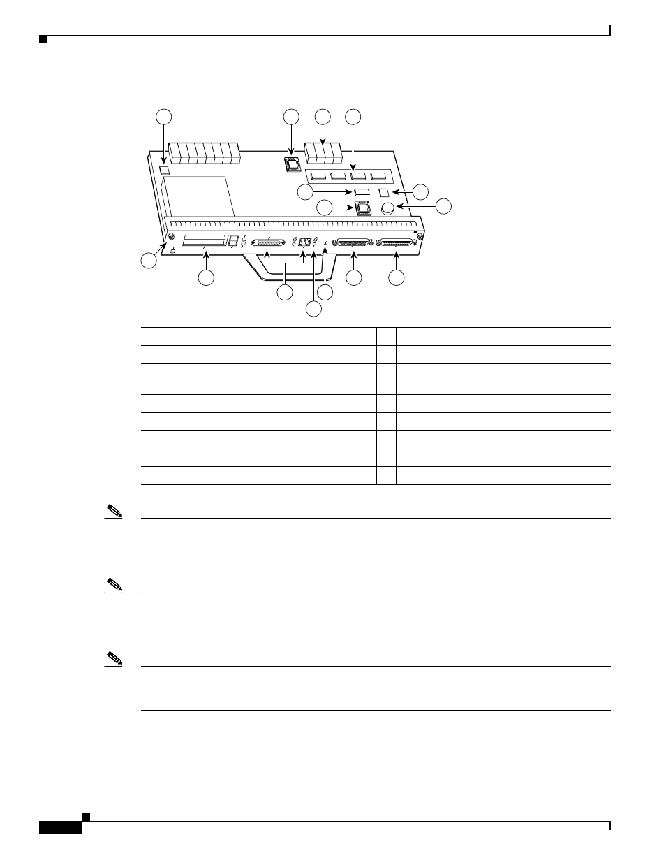
Figure 1-18
C7200-I/O-FE—With MII and RJ-45 Fast Ethernet Receptacles (Version 2)
Note
Your I/O controller with the MII and RJ-45 Fast Ethernet receptacles (C7200-I/O-FE) might look like
, or it might look like
. There is no functional difference between these two
I/O controllers with the Fast Ethernet port.
Note
In
, the NVRAM is replaced by an SRAM component (U14) that is made to act like the
NVRAM by the addition of some external components, one of which is the button-type lithium battery
labeled “Battery for SRAM.”
Note
Your I/O controller without the Fast Ethernet port (C7200-I/O) might look like
, or it might
look like
. There is no functional difference between these two I/O controllers without the
Fast Ethernet port.
1
Temperature sensor
9
Captive installation screw
2
FPGA configuration PROM (U9)
10 PC Card slots
3
Midplane connectors
11 Optional Fast Ethernet interface (MII port and
RJ-45 port)
4
4-MB Flash memory (soldered) (U10–U13)
12 LEDs
5
SRAM (U14)
13 CPU reset button
6
Boot EPROM (U4)
14 Auxiliary port
7
Temperature sensor
15 Console port
8
Battery for SRAM
84523
AUX
CONSOLE
PCMCIA
EJECT
SLOT 0
SLOT
1
FE MII
FAST ETHERNET INPUT/OUTPUT CONTROLLER
RJ45
CPU RESET
M
II E
N
R
J4
5
E
N
R
J4
5
LIN
K
I/O
P
W
R
O
K
ENABLED
10
12
9
13
15
14
1
2
3
4
7
8
11
6
5