Figure 1-7, Table 1-6, List – Cisco 7200 VXR User Manual
Page 18
1-18
Cisco 7200 VXR Installation and Configuration Guide
OL-5013-09
Chapter 1 Cisco 7200 VXR Product Overview
Field-Replaceable Units
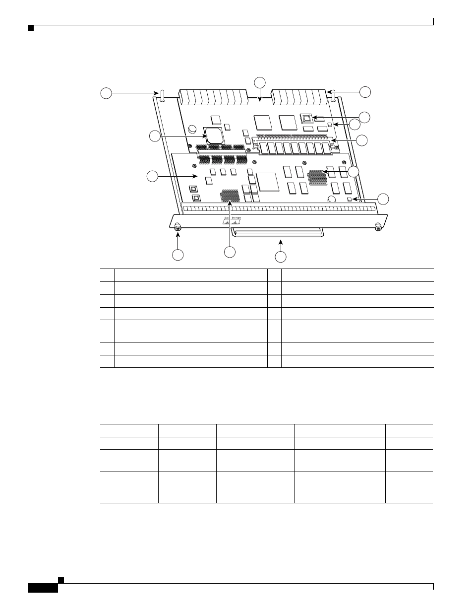
Figure 1-7
NSE-1
lists the NSE-1 memory specifications, and
lists the NSE-1 factory-installed
SDRAM configurations and their product numbers.
1
Network controller board
8
Midplane connectors
2
Keying post
9
Boot ROM (U1)
3
System controller
10 Temperature sensor
4
Processor engine board
11 SDRAM
5
Captive installation screw
12 Parallel eXpress Forwarding engine (PXF
processor)
6
RM7000 microprocessor
13 Temperature sensor
7
Handle
66418
NETWORK PROCESSING ENGINE-200
1
8
5
7
6
3
2
4
9
10
11
12
13
Table 1-6
NSE-1 Memory Specifications
Memory Type
Size
Quantity
Description
Location
1
SDRAM
128 or 256 MB
1 SDRAM slot
128- or 256-MB DIMM
U15
Boot ROM
512 KB
1
OTP ROM for the ROM
monitor program
U1
Primary cache
16 KB
(instruction),
16 KB (data)
—
RM7000 processor,
primary internal cache
U22
- ASA 5505 (1994 pages)
- OL-15491-01 (268 pages)
- WUSB600N (43 pages)
- 10000 (556 pages)
- 10000 (12 pages)
- 3825 (358 pages)
- WRV54G (101 pages)
- WUSB54GC (33 pages)
- 2600 Series (10 pages)
- DPQ2202 (38 pages)
- 1600 (13 pages)
- WRT320N (53 pages)
- 1701 (10 pages)
- 300 (16 pages)
- 3200 Series (60 pages)
- 2900 SERIES XL (138 pages)
- 4430 (12 pages)
- 1005 (6 pages)
- 3500 Series (8 pages)
- GigaStack WS-X3500-XL (58 pages)
- WIRELESS-G WRT54GP2 (112 pages)
- 1604 (22 pages)
- 3600 Series (18 pages)
- WIRELESS LAN CONTROLLER OL-17037-01 (80 pages)
- DPC3000 (36 pages)
- 3545 MCU (56 pages)
- WRT110 (48 pages)
- 7300-6T3 (54 pages)
- 10BASE-FL (40 pages)
- 340 (62 pages)
- 1700 (88 pages)
- 1700 (14 pages)
- 12000 (60 pages)
- 3600 (18 pages)
- 1800 Series (12 pages)
- 2000 (6 pages)
- ACE XML OL-13877-01 (12 pages)
- 10720 (26 pages)
- 10008 (38 pages)
- 10008 (48 pages)
- 1-PORT G.SHDSL 2600 (22 pages)
- XM Universal Gateways Cisco AS5400XM (100 pages)
- 1710 (12 pages)
- WRTP54G (114 pages)
- 7201 (4 pages)