Feature menu controe adjustments – Philips Magnavox 7P5441C199 User Manual
Page 10
Attention! The text in this document has been recognized automatically. To view the original document, you can use the "Original mode".
□
F
eature
M
enu
C
ontroe
A
djustments
PK Ti Ri; SOI R( i;
J
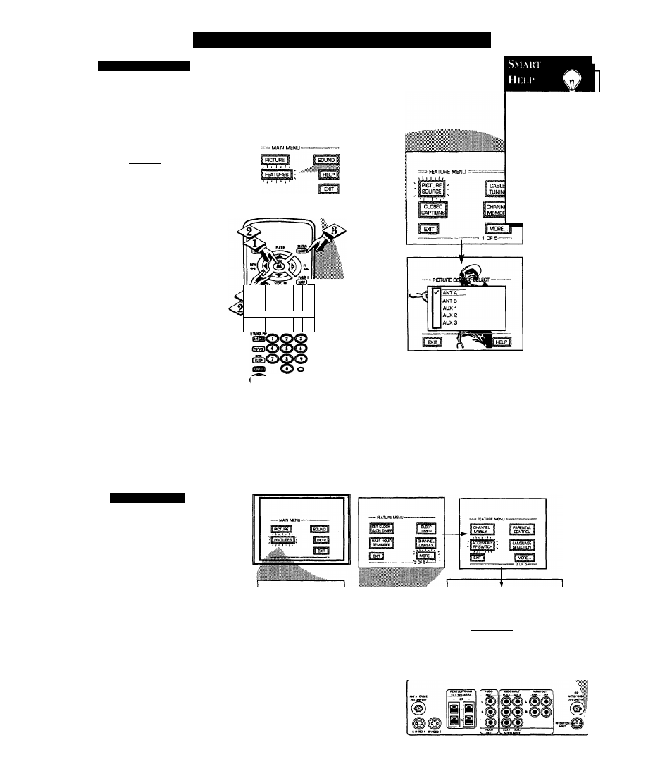
^he picture for the TV can come
through either the ANTENNA
plug or the AUDIOIVIDEO INput
jacks (on the rear of the TV). The
Picture Source control simply tells
the TV which one of these picture
sources it is to show on the TV
L
beoin
I
Select PICTURE SOURCE
SELECT control.
With the FEATURES MENU on
screen, move the REEyiighlight
with the MENU (M) 4 • ► buttons.
Then press the MEiW button.
<|> Press the MENU
AT
buttons
to move the RED highlight. Press
the MENU button to turn the
desired PICTURE SOURCE
control ON (i>).
ANT A or B- for a picture signal
coming from either the ANT(enna)
A or B Input plugs on the TV.
AUX 1- for a picture signal
coming from the AUX 1 Video
Input jack on the rear of the TV.
AUX 2- for a picture signal
coming from the AUX 2 Video
Input jack on the rear of the TV.
AUX 3- for a picture signal
coming from the Video Input jack
on the front of the TV.
Press the STATUS button to
clear the screen.
R1 S\M I ( I I K R
A
n optional RF Switcher is available
that will allow an AntennalCable TV
signal and another video accessory
(VCR, Video Disc Player, etc.) to be
connected to the TV at the same time.
Connection instructions are given with
the accessory RF Switcher, but be sure
to turn the TV’s power OFF (and
unplug its AC power cord) when
connecting the RF Switcher to the RF
Switch Input jack on the rear of the TV.
Replug the TV’s AC Power Cord into
the wall outlet and turn the TV ON. The
TV’s Picture Source Menu will now
show an Accessory Signal Source option
available for selection.
The accessory RF Switcher can be
purchased or ordered from your dealer.
If your dealer does not carry the
accessory, call the Information Center
number (listed with your warranty) for
further assistance.
^ O
o
Wi il «w» Ml Wig>
PIP
MO p e
Remember, s
the AUX 1, AUX
2, and AUX 3
modes must have a
video signal source
connected (to their
INPUT plug) or the
TV screen will be
blank. (See page 28
for connection
details).
— =«-
PII
a
^
i
~~1
Q ANT/CABLE
10