5 cable connection, 1 combination cable connection, 2 system layout – IC Realtime 1.3 Megapixel 18X PTZ Network Camera with Up-to 300 ft IR (ICIPMP1808IR) User Manual
Page 33
27
5 Cable Connection
5.1 Combination Cable Connection
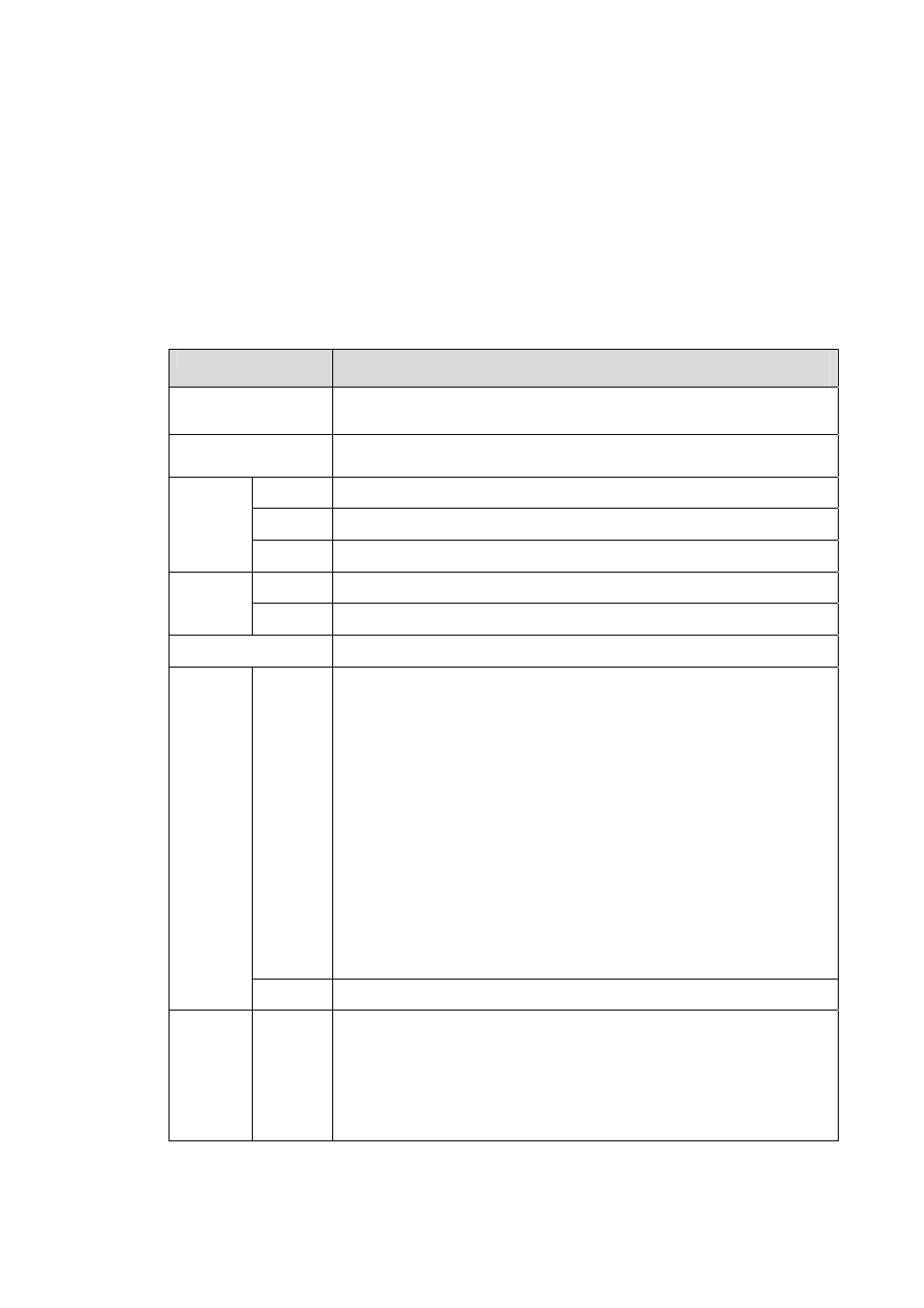
The speed dome combination cable includes network cable, audio/video cable connection port, RS485
connection port, alarm input and output port. Please refer to the label for detailed information.
z
Please note the IE6 does not support alarm upload function. Please use IE7 or higher version.
z
If it is your first time to boot up the WEB on the Windows 7 OS, please right click the Internet
Explorer icon on the desktop and then select “Run as Administrator”.
z
Slight difference may be found in the port amount since some functions are optional.
Name
Function
POWER
GND
Power port. Connect to the power cable.
GND: ground end.
485A
485B
RS485 remote control.
OUT
Audio output port.
GND Ground
port.
AUDIO
IN
Audio input port.
GND Ground
port.
VIDEO
OUT
Video output port.
LAN
Network port. Connect to network cable.
z
Seven alarm input channels. It is to receive relay signal from the
external alarm source. You can go to dome menu to activate
specified preset or patter.
z
When the activation mode is NO (normal open), dome alarms
when there is low voltage. High voltage will not activate the
alarm.
z
When the activation mode is NC (normal close), dome alarms
when there is high voltage. Low voltage will not activate the
alarm.
Note:
z
Dome alarm input message is ground mode.
z
Dome alarm input signal are two modes: normal open and
normal close.
z
The default setup: 7-channel alarm input.
ALARM
IN
GND
Alarm input ground end.
ALARM
OUT
2
z
Two alarm output channels. When there is an alarm from current
channel, system activates relay or not.
z
Alarm output relay default setup is NO.
z
The default setup: 2-channel alarm output.
5.2 System Layout