Build the center panel build the wing – Great Planes SlowPoke Sport 40 Kit - GPMA0492 User Manual
Page 9
❏ ❏
9. Using your marks as a guide, carefully drill a 1/8"
diameter hole into each elevator’s leading edge, approximately
3/4" deep.
❏ ❏
10. Cut a 1/8" deep groove from the elevator root to the
hole you just drilled. Hint:
This can be easily done using a
piece of sharpened 1/8" brass tubing or by using a Great
Planes Groove Tube.
❏
11. Insert the elevator joiner wire into the elevators and
check the combined parts for flatness and also that their
leading edges are straight. Carefully bend the joiner wire as
needed to obtain proper alignment. Check that the overall
length of the elevators matches the length of the stab. Once
satisfied with the alignment and fit, remove the joiner wire,
noting which end goes where. Roughen both “torque arms”
with coarse sandpaper or a file.
❏ ❏
12. Round off each elevator’s trailing edge and the stab
leading edge. Draw a centerline on their leading edges,
then sand both to a “V” as shown on the plan.
❏
13. Pack the joiner wire hole in only one elevator with
6-minute epoxy, then insert the joiner wire completely.
Without using any epoxy on the other elevator, slide it
onto the joiner wire and once again check for alignment with
a straightedge. Once the epoxy has cured, clean up the
leading edge with medium sandpaper and set both
elevators aside. Note: You will glue the other half of the
joiner wire in position during final assembly, after the model
is covered, so don’t get ahead of yourself just yet.
Well that was pretty painless wasn’t it? The tail feathers are
done and now we can move on to the bigger stuff. Clean off
your bench, cover the wing plan with wax paper or Plan
Protector and let's get going on the center section of the wing.
NOTE: The wing panels are built “right-side up” over
the plan.
Work on a flat surface over the plan covered with wax paper
or Great Planes Plan Protector. Refer to the plan and
die-cut patterns on pages 4 and 5 to identify and position
the parts.
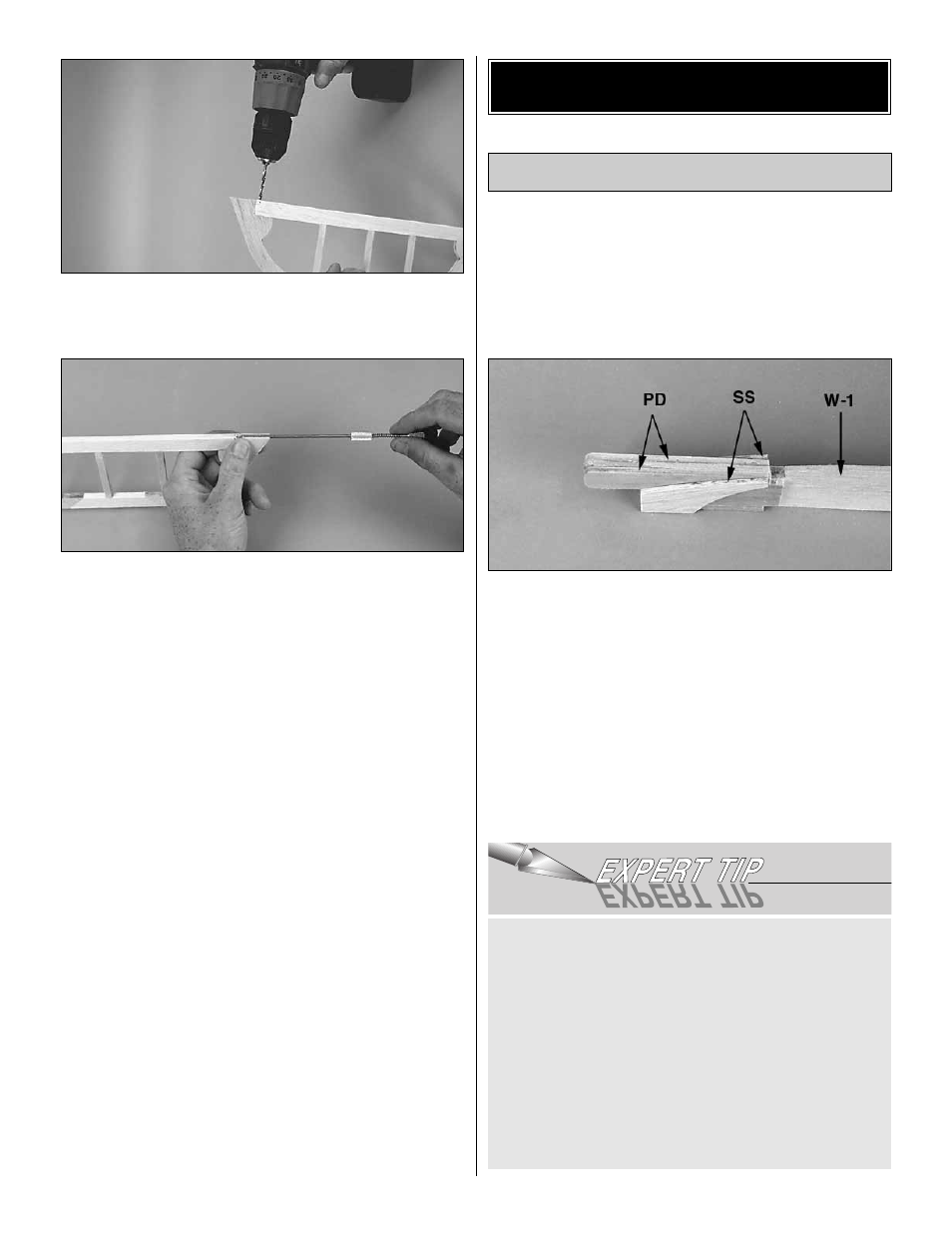
❏
1. Locate one 1/8" die-cut balsa W-1 rib, two 1/8" die-cut
ply wing plug doublers (PD) and two 3/32" die-cut balsa
sheeting supports (SS). Use medium CA to glue one wing
plug doubler to each side of the W-1 rib, aligned with the
forward end. Glue one 3/32" sheeting support to each side
of the plug doublers, flush with the bottom edge and LE.
❏
2. Cut four 1/16" x 3" x 30" balsa sheets into twelve 8-5/8"
long pieces. True up the edges. Refer to the
Expert Tip that
follows, then edge glue six pieces together to make the
bottom skin and six to make the top skin. The skins will
measure roughly 8-5/8" x 18". Trim one skin to 17-1/8". This
will be used on the bottom of the center panel.
CA is much harder than balsa, so when you sand edge
glued sheets you will usually end up with a ridge along
the joint. To avoid this problem the Great Planes Model
Shop team have reverted to using ordinary wood glue for
this application. We prefer Wood Glue as it sets quickly, is
water resistant and sands easily. We put a blob of the glue
on a sheet of wax paper, then apply it to the edge of the
wood with a finger-tip. After joining the sheets, wipe off
any excess with a tissue, then use a couple of strips of
masking tape to hold the sheets together while the glue
sets. Sand the joint by using a sanding block and fresh
220-grit sandpaper. Work the block in a circular motion
across the joint until smooth.
Build the Center Panel
BUILD THE WING
9