Build the lower fuselage build the fuselage – Great Planes SlowPoke Sport 40 Kit - GPMA0492 User Manual
Page 16
the parts together and pin the LE and TE in alignment.
Repeat this operation for the other wing tip. Weight the
center section down flat on the board and recheck all joints.
Let the wing assembly fully cure before moving it. Once the
epoxy has cured, sand all joints smooth.
❏
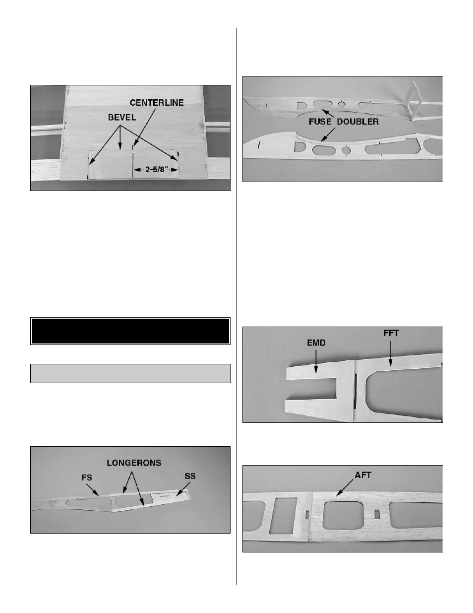
3. Locate one of the 1/8" die-cut ply wing bolt plates (BP).
Sand a bevel on one long side and both short ends. Measure
and mark a centerline 2-5/8" from one end. Measure and
mark a front to rear centerline on the bottom of the wing
center panel. With reference to the lines you just drew, center
and glue the wing bolt plate to the bottom of the wing with the
unbeveled edge flush with the TE of the wing.
Well, you are more than half way through the framing
stage, so clean up your workbench, have a soda and let’s
build the fuse.
NOTE: The fuse is built upside-down over the plan. The
plan sheet may be cut apart if space is a problem.
❏
1. Cover the side view of the fuse plan with wax paper or
Plan Protector.
❏
2. Position and pin a 1/8" die-cut ply fuse side (FS) over
the plan. Pin the 1/8" die-cut balsa stab saddle (SS) over
the plan at the aft end of the fuse. With reference to the
plan, cut a 1/8" x 1/2" x 36" balsa stick to make the top and
bottom longerons. Glue these sticks to the forward fuse
side and the stab saddle. Cut a short piece of leftover 1/8"
x 1/2" balsa stick to fit between the longerons at the rear of
the fuse aft of the stab saddle. Make a second fuse side to
match this one. Sand them smooth.
❏
3. Position the 1/8" die-cut ply former F-5 in the fuse side.
DO NOT GLUE. Use F-5 to locate the rear end of the
die-cut 1/8" ply fuse doubler (FD). Glue the doubler in
place. Repeat for the other fuse side. NOTE: Be sure to
build a left and a right fuse side.
❏
4. Cover the bottom view of the plan with wax paper or
Plan Protector. Position the 1/8 die-cut ply forward fuse top
(FFT) over the plan, being careful to align the engine
mount area exactly to the plan. If this piece is not correctly
placed you will build in the wrong engine thrust angle. As we
are building the fuse upside down, you should be able to
see a 3 degree
left thrust angle to the engine mount. Pin the
fuse top in position.
❏
5. Align and glue (use 6-minute epoxy) the 1/8" die-cut ply
engine mount doubler (EMD) to the surface of the fuse top
that is facing up.
❏
6. Glue both halves of the 1/8" die-cut balsa aft fuse top
(AFT) together. Position this assembly over the plan and
glue it to the forward fuse top. Pin it in position.
Build the Lower Fuselage
BUILD THE FUSELAGE
16