Great Planes SlowPoke Sport 40 Kit - GPMA0492 User Manual
Page 18
❏
16. Remove the fuse bottom from the board and sand off
any glue blobs or rough spots.
❏
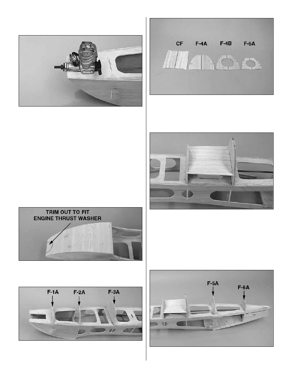
17. Position your engine in the engine mount with the
front edge of the thrust washer 3/16" ahead of the engine
mounting plate. Note: If the opening is too narrow, sand or
file both edges equally to make them wider. Mark the
location of the engine mounting holes. Hint:
a Great Planes
Dead Center marking tool is great for this purpose. Remove
the engine.
❏
18. To prevent splintering, hold a piece of leftover
hardwood under the engine mount, then drill a 1/8" diameter
hole through each mark. Turn the fuse over and install a 4-
40 blind nut in each hole. Seat them with a hammer or draw
them into position by temporarily bolting the engine in place
using the supplied 4-40 x 3/4" machine screws and #4
washers. Apply a drop of thin CA to each blind nut flange to
hold them in place. Don’t get CA into the threads.
❏
19. Use a 3/32" x 3" x 36" to sheet the bottom of the fuse from
the wing saddle to the nose. The grain must run across the
width of the fuse. Sand the sheeting flush with the fuse sides.
❏
20. Install 3/32" die-cut balsa formers F1A, F2A and F3A.
Make sure they are vertical with a square, then glue them
in place.
❏
21. Glue each of the two halves of the 1/8" die-cut balsa
cockpit floor (CF), F4A, F4B, and F5A together.
❏
22. Insert the forward tabs of the cockpit floor into the
notches of F3A. Insert die-cut balsa F4A into its notch, then
plug the floor into the notches in F4A. Insert die-cut balsa
former F4B behind F4A and check that everything is aligned
and centered. When everything is positioned, apply thin CA
to glue all of the pieces in place and to each other.
❏
23. Glue the 1/8" die-cut balsa formers F5A and F6A
in position.
18