Great Planes SlowPoke Sport 40 Kit - GPMA0492 User Manual
Page 17
❏
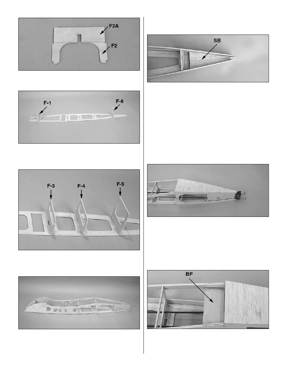
7. Locate 1/8" die-cut ply formers F2 and F2A. Glue them
together with thick CA.
❏
8. Install the 1/8" die-cut ply formers F1 and F6 in their
respective slots in the fuse top. Glue them in position with
thin CA.
❏
9. Install 1/8" die-cut ply formers F4, F5 at the
forward
edge of their respective notches and F3 at the rear of its
notch. Square and glue them to the fuse top.
❏
10. Align one of the fuse sides with F1 with the wing
saddle pointing up. Test fit the side along the length of the
fuse. When satisfied with the fit, tack glue it in place. Repeat
this procedure with the other fuse side.
❏
11. Insert the F2/2A former into the notches in the fuse
sides with the doubler facing the nose of the fuse.
❏
12. Slide the 1/8" die-cut balsa stab base (SB) into
position at the rear of the fuse. When satisfied that all
formers and the sides are aligned and everything is fitting
properly, wick thin CA into all joints to permanently glue the
fuse together. Apply medium or thick CA if needed to fill any
small gaps.
❏
13. Cut two 36" outer pushrod tubes to 22". Sand the
surface of the tubes with 80-grit sandpaper. Slide the tubes
into the rudder and elevator guide holes in formers F3 - F6
and out of the stab saddle. Glue them in place. Fill the
space around the exit slots with balsa filler, then sand the
tube flush with the stab saddle once the filler has dried.
❏
14. Insert, but do not glue a piece of leftover 1/4" x 1/2"
balsa between the fuse sides at the aft of the fuse to
simulate a tail post. Pin or clamp the sides to it, but be sure
it does not protrude past the bottom of the fuse sides. Use
a 3/32" x 3" x 36" to sheet the bottom of the fuse from F5 to
the tail. The grain must run across the width of the fuse.
Sand the sheeting flush with the fuse sides. The dummy tail
post may now be removed.
❏
15. Glue the three remaining 1/8" die-cut ply bolt plates
(BP) together with 6-minute epoxy. Use 6-minute epoxy to
glue the bolt plate assembly into the notch just forward of F5
and also to F5 itself.
17