Great Planes SlowPoke Sport 40 Kit - GPMA0492 User Manual
Page 23
❏
1. Assemble your tank and then hold it up inside the fuse
to mark the location of the fuel tubes. Drill a 1/4" hole for
both the supply tube and the pressure tube.
❏
2. With your engine in position, use a sharpened length of
wire to mark the location of the throttle pushrod onto the
firewall. Drill a 3/16" hole on this mark.
❏
3. Sand a 12" outer pushrod tube to roughen it up. Slide
it into the firewall and downward toward the servo tray. Cut
or drill additional passages as needed. Glue it to the firewall
leaving about 1/2" protruding.
❏
4. Install the fuel tank, leaving about 6" of fuel tubing
poking through the firewall. The tank should be padded with
1/2" foam rubber and supported by a couple of leftover
sticks glued to the fuse sides.
Mark the location of all hinges on the control surfaces
and mating surfaces. Start with the stab and elevators.
❏
1. Cut the hinge slot using a #11 blade in a standard #1
knife handle. The CA hinges provided have a thickness that
fits this type of slot very well. Trial fit the hinge into the slot.
If the hinge does not slide in easily, work the knife blade
back and forth in the slot a few times to provide more
clearance (it is really the back edge of the blade that does
the work here in widening the slot).
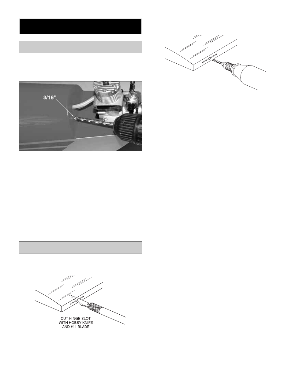
❏
2. Drill a 3/32" hole, 1/2" deep, in the center of the
hinge slot. If you use a Dremel
®
tool for this task, it will
result in a cleaner hole than if you use a slower speed
power or hand drill. Drilling the hole will twist some of the
wood fibers into the slot, making it difficult to insert the
hinge, so you should re-insert the knife blade, working it
back and forth a few times to clean out the slot.
❏
3. Cut 1" x 3/4" hinges from the hinge material provided.
Trial fit the hinges into the slots and temporarily attach the
control surface, to verify the fit and operation.
❏
4. Rather than just making a single slit, it is better to cut
away a narrow rectangle of covering to provide an adequate
opening for the CA glue to wick into the slot.
❏
5. Insert the hinges and install the control surface. Verify the
left-right positioning of the control surface and close up the
hinge gap to 1/32" or less. It is best to leave a very slight
hinge gap, rather than closing it up tight, to help prevent the
CA from wicking along the hinge line. Make sure the control
surface will deflect to the recommended throws without
binding. If you have cut your hinge slots too deep, the hinges
may slide in too far, leaving only a small portion of the hinge
in the control surface. To avoid this, you may insert a small
pin through the center of each hinge, before installing. This
pin will keep the hinge centered while you install the control
surface. Remove the pins before proceeding.
❏
6. Insert the elevator joiner wire through the opening in
the tail at the rear of the stab saddle. Fill the hole you drilled
in the elevator with 30-minute epoxy, then insert the wire arm
all the way in. Make sure that both elevators are level with
each other. Work all of the hinges into position and secure
them with a few drops of thin CA on both sides of each hinge.
❏
7. Cut the hinge slots for the rudder and test fit the rudder
to the fin with the tail gear in position. When satisfied with
the fit, remove the rudder. Then use 30-minute epoxy to
fasten the tail gear bearing into the fuse. Coat the wire
where it passes through the bearing with petroleum jelly to
prevent it from becoming glued to the bearing.
❏
8. Pack the tail gear hole in the rudder with epoxy, then
install the rudder in the same way as the elevator using
three hinges.
DRILL A 3/32" HOLE
1/2" DEEP, IN CENTER
OF HINGE SLOT
Install the Control Surfaces
Install the Tank & Throttle Pushrod
FINAL HOOKUPS & CHECKS
23