Great Planes Reactor Bipe 3D EP ARF - GPMA1580 User Manual
Page 9
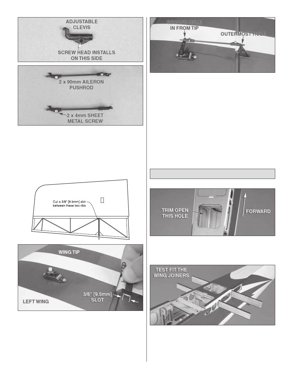
❏
5. Locate four adjustable clevises, four 2 x 4mm sheet
metal screws, and the two 2 x 90mm carbon fi ber pushrods.
Using 220-grit sandpaper, lightly sand the last 3/4" [19.1mm]
of each side of each pushrod. Slide a clevis on each end
of the pushrods and loosely thread a 2 x 4mm sheet metal
screw into each clevis. Insert the screw on the side of the
clevis that has the recessed hole. The other side of the clevis
is thicker for the screw threads to engage in.
❏
6. Cut a 3/8" [9.5mm] long slot in the lower wing ailerons
just behind the beveled edge of the aileron LE. The slot will
be cut between two closely spaced ribs directly ahead of
where you installed the aileron link horns.
❏
7. Clean the studs of the control horns with denatured
alcohol and glue the horns in place with epoxy or thick CA.
❏
8. Install each pushrod in the control horn so that the
clevis is in the outermost hole of the control horn. Install
the other side of the pushrod in the servo arm so that the
clevis is in the second outermost hole. This will require
you to temporarily remove and reinstall the servo arm, so
remember to reinstall the servo arm screw.
Install the Lower Wings
❏
1. Trim the covering from the opening (and reseal along
the edges with a covering iron), just behind the battery
access hatch on the bottom of the fuselage. This is where
the receiver will be installed later.
❏
2. Locate the front and rear wing joiners. Test fi t each
one inside of the fuselage. You should not need to force the
joiner into position. If a joiner is too tight, you may lightly
sand the fl at face and the upper or lower carbon edge of the
joiner until it will slide into place. Use only 220-grit sandpaper
for this.
9