Great Planes Reactor Bipe 3D EP ARF - GPMA1580 User Manual
Page 19
19
❏
2. Apply threadlocking compound to the prop adapter
screws and tighten the prop adapter onto the motor. Remove
the “X” mount that was included with the motor and retain the
four 3 x 8mm countersunk screws. Tighten all motor screws.
❏
3. Temporarily install the supplied wooden “X” mount using
the countersunk screws. Tighten the screws until the head is
1mm above the surface of the wooden “X” mount. Remove
the screws and the motor and harden the holes in the mount
with thin CA.
❏
4. Apply threadlocking compound to the screw threads
and reinstall the “X” mount with the screws.
❏
5. Apply threadlocking compound to four 3 x 10mm
machine screws and use four 3mm washers to attach the
motor to the motor mounting box.
❏
6. Connect the motor leads to the ESC. Any motor wire
can be connected to any ESC wire at this point.
Install the Radio
❏
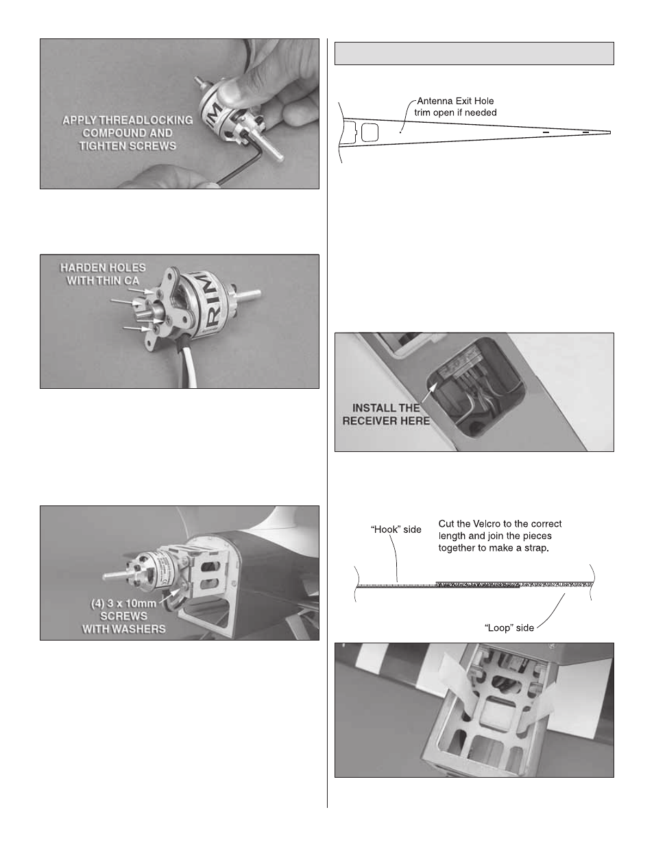
1. Use the sketch above to help you locate the pre-drilled
antenna exit hole. Trim the covering from the antenna exit
hole only! You may skip this step and the next step if you are
using a 2.4GHz spread spectrum receiver.
❏
2. Route your antenna lead through the hole and out of
the fuselage. Tape the end of the antenna to the side of the
tail skid.
❏
3. Plug your servo leads into their corresponding channels
on the receiver.
❏
4. Use double-sided servo tape to mount your radio
receiver to the back side of the forward wing spar. You may
apply 30-minute epoxy to the back side of the front wing spar
to help the double-sided tape stick better.
❏
5. Make a battery strap out of the included 5" [127mm]
hook and loop material and route it as shown.